
800-821-2686
614-420-4572
2783 Martin Rd.
Dublin, OH 43017
513-926-6186
9891 Montgomery, Rd.
Cincinnati, Ohio 45242
937-222-2269
2324 Stanley Avenue
Dayton, Ohio 45404
Local Technicians equal Great Service!!
800-821-2686
We have many “crash systems” and repair parts in stock to get your system up and operating the same day.
Our suppliers can provide us with almost any equipment including unusual and outdated brands. We can usually have your system operational by the next morning.
 Loading...
www.daytonohiotele.com/manuals/comdial/Comdial%20DSU%20II%20Installation%20Manual.pdf
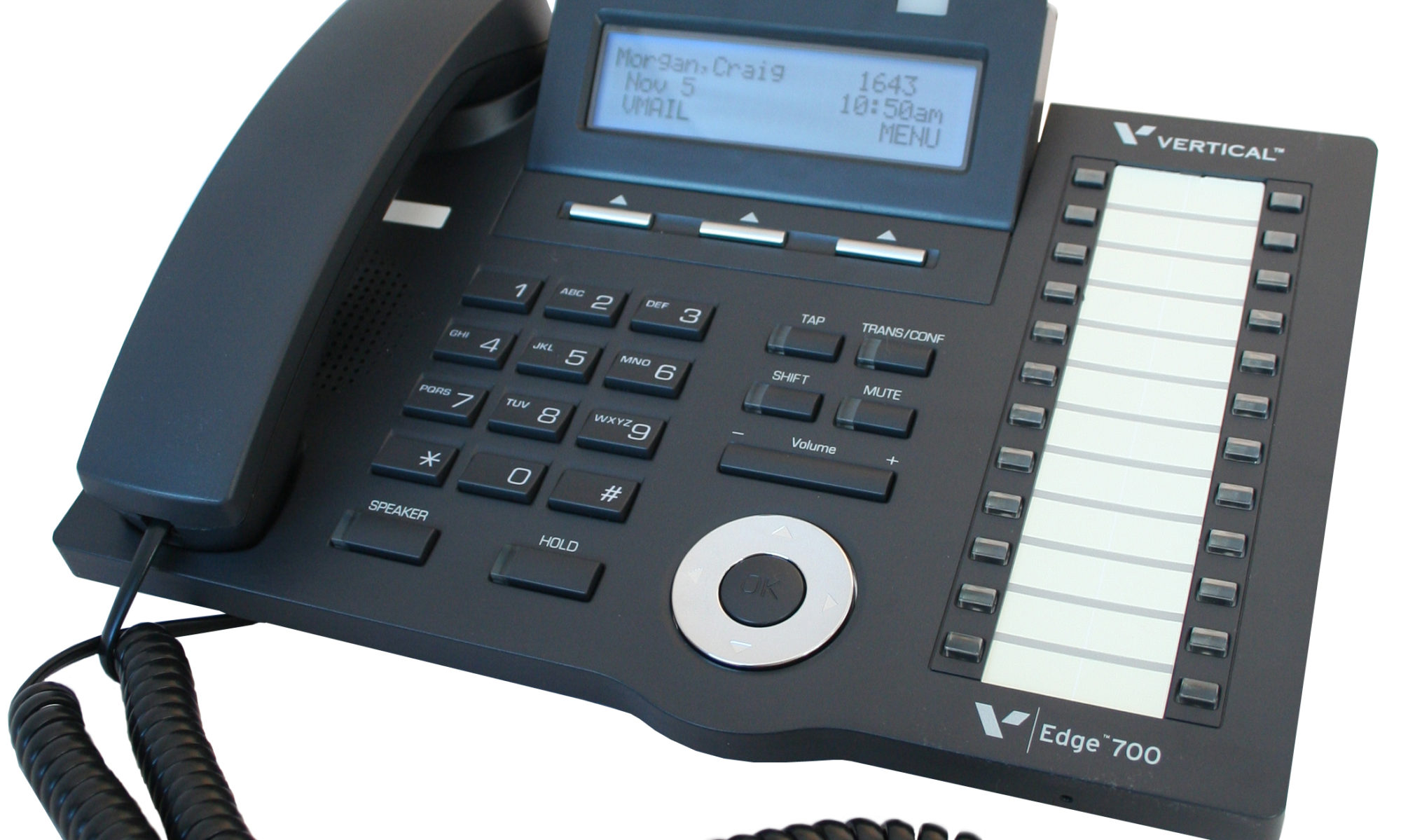
Our seasoned Technicians work on Vertical, Comdial, Nortel, Vodavi, Toshiba, AT&T, Avaya, Lucent, Panasonic, NEC and many others.
800-821-2686

6 I n s t a l l i n g D S S / B L F C o n s o l e s
The digital telephone system supports the installation and use of DigiTech DD32X, Impact IB64X, and Impression DU32X consoles at any available station port. The number of installed consoles is limited only by port availability; however, since a console complements a companion telephone located in an adjacent station port, you can use up to one-half of the available station ports for consoles. In addition, with the dual console feature (discussed later), a full two-thirds of the total station port capacity is available for console use. Comdial DSU
You can assign two consoles to one telephone, each taking its own station port. This feature is especially useful with DigiTech DD32X and Impression DU32X consoles and a J1632 system that has one or two JM408 expansion modules included with it. This dual console feature allows a station user to monitor up to 48 stations from one station location using 32-button consoles. Comdial DSU
Install the first console at the station port that is logic-paired with the station that you wish to complement. Install the second console at any station port except 10 or 11 and, using class of service programming, assign it to the same station port that is logic-paired with the first console.
D e t a i l i n g T h e D i g i t a l S t a t i o n P o r t L o g i c P a i r i n g 10–11 26–27 42–43 12–13 28–29 44–45 14–15 30–31 46–47 16–17 32–33 48–49 18–19 34–35 50–51 20–21 36–37 52–53 22–23 38–39 54–55 24–25 40–41 56–57
You can install the DSS/BLF console at any station port and assign it to a station without first installing a console at the station’s logic-paired port if you wish. This configuration is convenient for adding a console to an existing telephone installation that already has its logic-paired port occupied; however, do not use this configuration for assigning a console to station ports 10 and 12 because the console buttons will not be usable for programming. As discussed above, this feature is also useful for adding a second console to a station that already has a paired console installed with it.
The digital telephone system automatically recognizes a console when you connect it to a station port and automatically assigns the station intercom numbers to the console buttons for direct station selection (DSS) purposes with associated busy lamp field (BLF) status lights. However, the console buttons are fully programmable and the station user can customize them as he or she sees fit by programming them as DSS buttons or as automatic dialing (autodial) buttons. Comdial DSU Comdial DSU
When the user programs the buttons for DSS use, autodial capability is also available at a secondary level at each DSS button.
I M I 6 6 – 1 3 2 D S U I I D i g i t a l T e l e p h o n e S y s t e m
2 – 2 6 I n s t a l l i n g T h e D S U I I D i g i t a l T e l e p h o n e S y s t e m
The DSU II includes serial data ports for use. The common equipment cabinet provides these ports as standard modular jacks labeled COM 1 and COM 2 This section contains information on two stages of wiring these connections for data devices.
Section 2.12.1 explains connections from stations to modular jacks. Section 2.12.2 details wiring from the modular jack to the DSU.
2 . 1 2 . 1 M a k i n g M o d u l a r J a c k D a t a C o n n e c t i o n s
Modular jack connections are wiring connections from a station to a modular (wall) jack.
The system provides two serial data ports on the J0408 and four serial data ports on the J0816 and J1632 for use.
• When you use a personal computer (PC) to perform class of service programming or to load system software into the system, connect it to COM 1.
• When you use a serial data printer for SMDR, SMDA, COS printout, or Caller ID, connect it to the COM 2.
NOTE: The distance between a data device and the common equipment can be up to 500 feet in a quiet electrical environment. Some sites may require shielded cable for long runs. For longer distances, you must install limited distance modems to relay the data communications between the common equipment and a data device.
When preparing a cable for connection to a data device, refer to the manufacturer’s manual for the equipment being interfaced and make the following wiring connections:
• Wire the common equipment RD (data from device to common equipment) connection to the device TD (transmit data) connection.
• Wire the common equipment TD (data to device from common equipment) connection to the device RD (receive data) connection.
• Wire the common equipment SG (signal ground) connection to the device SG (signal ground) connection.
• If required for proper operation, wire the common equipment CTS (clear-to-send status from device to common equipment) connection to the device RTS (request-to-send) connection. Comdial DSU
NOTE: The common equipment requires a positive voltage, with respect to signal ground, in order to send data.
I M I 6 6 – 1 3 2 D S U I I D i g i t a l T e l e p h o n e S y s t e m
2 – 3 4 I n s t a l l i n g T h e D S U I I D i g i t a l T e l e p h o n e S y s t e m
You can connect a personal computer (PC) to the DSU II digital telephone system remotely through modems as described below. (For information on direct connection, refer to Section 2.12.1. ) Comdial DSU
You will need the following customer-supplied equipment:
• PC and appropriate software program, • Pair of data modems.
The data modems must be: “Hayes-compatible,” capable of 300-, 1200-, 2400-, or 9600-baud data speeds, and have auto-answer capability. Be sure to verify the auto-answer capability before purchasing the units. You are assured of best results if you employ modems of the same make and model at both the installation site and the remote programming site. Comdial DSU
Make the equipment connections per the following procedure:
1. Determine the signal needs of the modem from the user’s manual for it. (The digital telephone system only requires TD, RD, and SG but the modems may require more signals. Check with the modem manufacturer for special requirements).
2. Wire the proper connector (to match the data jack) on one end of a length of multiline cable.
3. Punch down the appropriate leads on the connector block.
4. Connect the network jack of the data modem to an outside telephone line. (If a line is not reserved for remote programming, have a line switch installed so that on site personnel can switch the outside telephone line between the data modem and the digital telephone system cabinet when you are going to perform remote programming.)
5. Refer to the user’s manual for the modem, and program the modem to automatically answer after the first ring.
6. Interface the PC with the modem at the programming site per the user’s manuals for the equipment be used. Comdial DSU
7. Establish a communications link for programming the system from a remote site.
• If you have had a line switch installed at the customer site, call someone there and ask them to set it for modem operation.
• After the outside line is connected to the modem, make the data link between the originating and the remote modems, and perform programming from your remote site just as if the PC was connected directly to the system. Comdial DSU
I M I 6 6 – 1 3 2 D S U I I D i g i t a l T e l e p h o n e S y s t e m
2 – 3 8 I n s t a l l i n g T h e D S U I I D i g i t a l T e l e p h o n e S y s t e m