
800-821-2686
614-420-4572
2783 Martin Rd.
Dublin, OH 43017
513-926-6186
9891 Montgomery, Rd.
Cincinnati, Ohio 45242
937-222-2269
2324 Stanley Avenue
Dayton, Ohio 45404
Local Technicians equal Great Service!!
800-821-2686

| Vertical SBX IP 320 Programming | 8.5M |
Vertical SBX IP 320
Basic System Features
General Information – – – – – – – – – – – – – – – – – – – – – – – – – – – – – – – 1-1
Reference Material – – – – – – – – – – – – – – – – – – – – – – – – – – – – – 1-1
About This Guide – – – – – – – – – – – – – – – – – – – – – – – – – – – – – – 1-2
Programming Guidelines – – – – – – – – – – – – – – – – – – – – – – – – – 1-2
911 Feature – – – – – – – – – – – – – – – – – – – – – – – – – – – – – – – – – – – – – 1-5
Attendant Service – – – – – – – – – – – – – – – – – – – – – – – – – – – – – – – – – 1-6
Assigning an Attendant – – – – – – – – – – – – – – – – – – – – – – – – – – 1-6
Attendant Call & Queuing – – – – – – – – – – – – – – – – – – – – – – – – 1-7
Attendant Forward – – – – – – – – – – – – – – – – – – – – – – – – – – – – – 1-8
Attendant Intrusion – – – – – – – – – – – – – – – – – – – – – – – – – – – – – 1-8
Attendant Override – – – – – – – – – – – – – – – – – – – – – – – – – – – – – 1-9
Attendant Recall – – – – – – – – – – – – – – – – – – – – – – – – – – – – – – 1-10
LCD Date/Time Display – – – – – – – – – – – – – – – – – – – – – – – – – 1-11
Day/Night Service – – – – – – – – – – – – – – – – – – – – – – – – – – – – – 1-12
Outgoing Access – – – – – – – – – – – – – – – – – – – – – – – – – – – – – – 1-15
DSS/BLF Consoles – – – – – – – – – – – – – – – – – – – – – – – – – – – – 1-16
ICM Box Music – – – – – – – – – – – – – – – – – – – – – – – – – – – – – – – 1-17
Station Feature Cancel – – – – – – – – – – – – – – – – – – – – – – – – – 1-18
Call Control – – – – – – – – – – – – – – – – – – – – – – – – – – – – – – – – – – – – 1-18
Account Code – – – – – – – – – – – – – – – – – – – – – – – – – – – – – – – – 1-18
Authorization Code – – – – – – – – – – – – – – – – – – – – – – – – – – – – 1-20
Automatic Call Release – – – – – – – – – – – – – – – – – – – – – – – – – 1-22
Class Of Service (COS) – – – – – – – – – – – – – – – – – – – – – – – – – 1-23
System Speed Zone – – – – – – – – – – – – – – – – – – – – – – – – – – – 1-29
Walking Class of Service (Walking COS) – – – – – – – – – – – – 1-30
Call Handling – – – – – – – – – – – – – – – – – – – – – – – – – – – – – – – – – – – 1-31
Alarm – – – – – – – – – – – – – – – – – – – – – – – – – – – – – – – – – – – – – – 1-31
Issue 2.1 December 2008
Contents TOC-2
SBX IP 320 Programming & Operations Guide
Automatic Incoming Fax Transfer – – – – – – – – – – – – – – – – – – 1-32
Automatic Privacy – – – – – – – – – – – – – – – – – – – – – – – – – – – – – 1-33
Barge In – – – – – – – – – – – – – – – – – – – – – – – – – – – – – – – – – – – – 1-34
Background Music (BGM) – – – – – – – – – – – – – – – – – – – – – – – – 1-35
Call Log (Models 7208D/7224D only) – – – – – – – – – – – – – – – – 1-37
Camp-on – – – – – – – – – – – – – – – – – – – – – – – – – – – – – – – – – – – – 1-38
Chime Bell – – – – – – – – – – – – – – – – – – – – – – – – – – – – – – – – – – – 1-39
CLI Display – SLT Feature – – – – – – – – – – – – – – – – – – – – – – – – 1-41
Company Directory – – – – – – – – – – – – – – – – – – – – – – – – – – – – – 1-42
Data Line Security – – – – – – – – – – – – – – – – – – – – – – – – – – – – – 1-44
Dialing Security – – – – – – – – – – – – – – – – – – – – – – – – – – – – – – – 1-45
Distinctive Ring Tone – – – – – – – – – – – – – – – – – – – – – – – – – – – 1-45
Do Not Disturb (DND) – – – – – – – – – – – – – – – – – – – – – – – – – – – 1-46
Do Not Disturb (DND) Forward to Voice Mail – – – – – – – – – – 1-47
Do Not Disturb (One Time DND) – – – – – – – – – – – – – – – – – – – 1-47
Do Not Disturb (DND) with Pre-Selected Message – – – – – – 1-48
Emergency Intrusion – – – – – – – – – – – – – – – – – – – – – – – – – – – – 1-49
Extend CO-to-CO Connection – – – – – – – – – – – – – – – – – – – – – 1-50
Flash – – – – – – – – – – – – – – – – – – – – – – – – – – – – – – – – – – – – – – – 1-51
Flex Buttons – – – – – – – – – – – – – – – – – – – – – – – – – – – – – – – – – 1-52
Forced Hands-Free Mode – – – – – – – – – – – – – – – – – – – – – – – – 1-55
Forced Trunk Disconnect – – – – – – – – – – – – – – – – – – – – – – – – 1-56
Headset – – – – – – – – – – – – – – – – – – – – – – – – – – – – – – – – – – – – 1-56
Hot Desk – – – – – – – – – – – – – – – – – – – – – – – – – – – – – – – – – – – – 1-58
In-Room Indication – – – – – – – – – – – – – – – – – – – – – – – – – – – – – 1-60
Intercom Signal Mode (HF/TN/PV) – – – – – – – – – – – – – – – – – – 1-61
Intercom Tenancy Group – – – – – – – – – – – – – – – – – – – – – – – – 1-62
Message Wait and Call Back – – – – – – – – – – – – – – – – – – – – – – 1-63
Message Wait Indicator LEDs – – – – – – – – – – – – – – – – – – – – – 1-64
Message Wait Indication (MWI) – SLT Feature – – – – – – – – – 1-67
Messages (Customized Display Text) – – – – – – – – – – – – – – – 1-67
Mobile Extension – – – – – – – – – – – – – – – – – – – – – – – – – – – – – – 1-70
Music On Hold (MOH) – – – – – – – – – – – – – – – – – – – – – – – – – – 1-73
Issue 2.1 December 2008
Contents TOC-3
SBX IP 320 Programming & Operations Guide
Mute – – – – – – – – – – – – – – – – – – – – – – – – – – – – – – – – – – – – – – 1-74
On-Hook Dialing – – – – – – – – – – – – – – – – – – – – – – – – – – – – – – 1-75
Remote Mobile Extension Control – – – – – – – – – – – – – – – – – – 1-76
Station Call Coverage – – – – – – – – – – – – – – – – – – – – – – – – – – 1-77
Station Name Programming (Dial-by-Name) – – – – – – – – – – 1-78
Station Port Blocking – – – – – – – – – – – – – – – – – – – – – – – – – – – 1-80
Station User Programming – – – – – – – – – – – – – – – – – – – – – – – 1-80
Station Relocation – – – – – – – – – – – – – – – – – – – – – – – – – – – – – 1-81
Station Serial Call (Internal Calls Only) – – – – – – – – – – – – – – 1-82
Time & Date Setup (Digital network Only) – – – – – – – – – – – – 1-82
Voice Over – – – – – – – – – – Vertical SBX IP 320 – – – – – – – – – – – – – – – – – – – – – – – – 1-82
Wakeup – – – – – – – – – – – – – – – – – – – – – – – – – – – – – – – – – – – – 1-84
Conference Calls – – – – – – – – – – – – – – – – – – – – – – – – – – – – – – – – 1-86
Multi-line Conferences – – – – – – – – – – – – – – – – – – – – – – – – – – 1-86
Conference Room – – – – – – – – – – – – – – – – – – – – – – – – – – – – – 1-87
Paging Conference – – – – – – – – – – – – – – – – – – – – – – – – – – – – 1-90
SLT Conference (Brokers Call) – – – – – – – – – – – – – – – – – – – – 1-91
External Device Control – – – – – – – – – – – – – – – – – – – – – – – – – – – 1-91
Door Open – – – – – – – – – – – – – – – – – – – – – – – – – – – – – – – – – – 1-91
Doorboxes – – – – – – – – – – – – – – – – – – – – – – – – – – – – – – – – – – 1-92
Loud Bell – – – – – – – – – – – – – – – – – – – – – – – – – – – – – – – – – – – 1-94
Hunt Groups – – – – – – – – – – – – – – – – – – – – – – – – – – – – – – – – – – – 1-95
Circular/Terminal Hunt Groups – – – – – – – – – – – – – – – – – – – – 1-98
Unified Call Distribution Groups (UCD Groups) – – – – – – – 1-100
Ring Hunt Groups – – – – – – – – – – – – – – – – – – – – – – – – – – – – 1-112
Voice Mail Hunt Groups (SLT only) – – – – – – – – – – – – – – – – 1-114
Pick-Up Groups – – – – – – – – – – – – – – – – – – – – – – – – – – – – – 1-115
Hunt Group Name Service – – – – – – – – – – – – – – – – – – – – – – 1-115
Incoming Call Pickup – – – – – – – – – – – – – – – – – – – – – – – – – – – – 1-117
CO Line Name – – – – – – – – – – – – – – – – – – – – – – – – – – – – – – 1-117
Customer Call Routing (CCR) with Voice Mail – – – – – – – – 1-117
Direct Inward Dialing (DID) – – – – – – – – – – – – – – – – – – – – – 1-123
DID Call Routing with Incoming CLI – – – – – – – – – – – – – – – 1-126
Issue 2.1 December 2008
Contents TOC-4
SBX IP 320 Programming & Operations Guide
DID/DISA Call Routing for Station in DND or Pre-selected
Message Mode – – – – – – – – – – – – – – – – – – – – – – – – – – – – – – 1-128
Direct Inward System Access (DISA) – – – – – – – – – – – – – – – 1-128
Preferred Line Answer (PLA) – – – – – – – – – – – – – – – – – – – – – 1-131
Ring Assignment – – – – – – – – – – – – – – – – – – – – – – – – – – – – – 1-132
Universal Night Answer (UNA) – – – – – – – – – – – – – – – – – – – – 1-133
IP Phone Reroute Service – – – – – – – – – – – – – – – – – – – – – – – – – 1-134
ISDN Service – – – – – – – – – – – – – – – – – – – – – – – – – – – – – – – – – – 1-134
Calling Line Identification Presentation (CLI) – – – – – – – – – – 1-135 Vertical SBX IP 320
Calling Party Number (CPN) Service – – – – – – – – – – – – – – – 1-142
Linked Stations – – – – – – – – – – – – – – – – – – – – – – – – – – – – – – – – – 1-143
Executive/Secretary Pairs – – – – – – – – – – – – – – – – – – – – – – – 1-143
Linked-Pair Stations – – – – – – – – – – – – – – – – – – – – – – – – – – – 1-145
Outgoing Call Access – – – – – – – – – – – – – – – – – – – – – – – – – – – – – 1-146
Basic Access – – – – – – – – – – – – – – – – – – – – – – – – – – – – – – – – 1-146
Call Time Restriction – – – – – – – – – – – – – – – – – – – – – – – – – – 1-149
CO Line Queuing – – – – – – – – – – – – – – – – – – – – – – – – – – – – – 1-150
CO Step Call – SLT Phones Only – – – – – – – – – – – – – – – – – – 1-151
Emergency Call Service – – – – – – – – – – – – – – – – – – – – – – – – 1-151
Hot Line & Warm Line – – – – – – – – – – – – – – – – – – – – – – – – – – 1-151
Least Cost Routing (LCR) – – – – – – – – – – – – – – – – – – – – – – – 1-153
Memory Dialing – – – – – – – – – – – – – – – – – – – – – – – – – – – – – – 1-161
Private Line (Digital Phones only) – – – – – – – – – – – – – – – – – 1-170
Paging – – – – – – – – – – – – – – – – – – – – – – – – – – – – – – – – – – – – – – – 1-170
Internal, External, All-Call, and Meet-Me Page – – – – – – – – 1-170
Pre-recorded (VMIB) Message – – – – – – – – – – – – – – – – – – – 1-173
SOS Paging (Digital Phones only) – – – – – – – – – – – – – – – – – 1-174
Push-to-Talk (PTT) – (Nomad IP Phones only – – – – – – – – – 1-175
Rerouting – – – – – – – – – – – – – – – – – – – – – – – – – – – – – – – – – – – – – 1-175
Call Forward – – – – – – – – – – – – – – – – – – – – – – – – – – – – – – – – 1-175
Call Transfer – – – – – – – – – – – – – – – – – – – – – – – – – – – – – – – – 1-181
Holding and Parking – – – – – – – – – – – – – – – – – – – – – – – – – – – 1-184
Pick-Up – – – – – – – – – – – – – – – – – – – – – – – – – – – – – – – – – – – – 1-188
Issue 2.1 December 2008
Contents TOC-5
SBX IP 320 Programming & Operations Guide
Software Upgrade – – – – – – – – – – – – – – – – – – – – – – – – – – – – – – 1-191
LAN Connection – – – – – – – – – – – – – – – – – – – – – – – – – – – – – 1-191
Modem Connection – – – – – – – – – – – – – – – – – – – – – – – – – – – 1-193
Serial (COM port) – – – – – – – – – – – – – – – – – – – – – – – – – – – – 1-195
Station Message Detail Recording (SMDR) – – – – – – – – – – – – 1-197
Print-out – Lost Call – – – – – – – – – – – – – – – – – – – – – – – – – – – 1-200
Supplementary Service – – – – – – – – – – – – – – – – – – – – – – – – – – – 1-203 Vertical SBX IP 320
Collect Call Blocking for E1-R2 and LCO (for Brazil) – – – – 1-203
Message Wait Notification to Mobile Extension (SIP Trunks only)
1-204
Traffic Analysis – – – – – – – – – – – – – – – – – – – – – – – – – – – – – – – – 1-204
Attendant Reports – – – – – – – – – – – – – – – – – – – – – – – – – – – – 1-206
Call Reports – – – – – – – – – – – – – – – – – – – – – – – – – – – – – – – – 1-207
CO Reports – – – – – – – – – – – – – – – – – – – – – – – – – – – – – – – – 1-209
Hardware (H/W) Unit Reports – – – – – – – – – – – – – – – – – – – – 1-210
Other Programming Tables – – – – – – – – – – – – – – – – – – – – – – – – 1-212
Station Attributes I (PGM 111) – – – – – – – – – – – – – – – – – – – 1-212
Station Attributes II (PGM 112) – – – – – – – – – – – – – – – – – – – 1-213
Station Attributes III (PGM 113) – – – – – – – – – – – – – – – – – – 1-214
Station Attributes IV (PGM 114) – – – – – – – – – – – – – – – – – – 1-215
SMDR Account Group (PGM 124) – – – – – – – – – – – – – – – – 1-216
Copy DSS Button (PGM 125) – – – – – – – – – – – – – – – – – – – – 1-217
Station IP List (PGM 126) – – – – – – – – – – – – – – – – – – – – – – 1-217 Vertical SBX IP 320
Display Station Number By COS / By CO Group (PGM 130-131)
1-218
CO Line (PGM 140-146) – – – – – – – – – – – – – – – – – – – – – – – 1-218
Slot Base Program (PGM 155) – – – – – – – – – – – – – – – – – – – 1-223
System Data (PGM 160-184) – – – – – – – – – – – – – – – – – – – – 1-224
System Timers (PGM 180-184) – – – – – – – – – – – – – – – – – – 1-232
DCOB Attribute (PGM 186-187) – – – – – – – – – – – – – – – – – – 1-235
ISDN System Base Program – – – – – – – – – – – – – – – – – – – – 1-237
Tables – – – – – – – – – – – – – – – – – – – – – – – – – – – – – – – – – – – – 1-238
Nation Specific (PGM 400-424) – – – – – – – – – – – – – – – – – – 1-239
Initialization (PGM 450) – – – – – – – – – – – – – – – – – – – – – – – – 1-244
Issue 2.1 December 2008
Contents TOC-6
SBX IP 320 Programming & Operations Guide
Print Prot Database (PGM 451) – – – – – – – – – – – – – – – – – – – 1-245 Vertical SBX IP 320
Appendix A Networking Services
Internet Protocol (H.450) – – – – – – – – – – – – – – – – – – – – – – – – – – – A-1
Networking Basics – – – – – – – – – – – – – – – – – – – – – – – – – – – – – A-1
Display Messages (Absent Text Message) – – – – – – – – – – – – A-2
Attendant Call Service (CAS) – – – – – – – – – – – – – – – – – – – – – A-2
Busy Lamp Field (BLF) – – – – – – – – – – – – – – – – – – – – – – – – – – A-3
Call Completion – – – – – – – – – – – – – – – – – – – – – – – – – – – – – – – A-4
Call Offer – – – – – – – – – – – – – – – – – – – – – – – – – – – – – – – – – – – – A-5
Centralized SMDR for Network (Transit) Calls – – – – – – – – – – A-6
Centralized Voice Mail System (VMS) – – – – – – – – – – – – – – – A-7
CO Ring Assignment – – – – – – – – – – – – – – – – – – – – – – – – – – – A-7
CO Transit – In – – – – – – – – – – – – – – – – – – – – – – – – – – – – – – – – A-8
CO Transit – Out – – – – – – – – – – – – – – – – – – – – – – – – – – – – – – – A-9
Do-Not-Disturb (DND) with Network Calls – – – – – – – – – – – – A-10
Identification Service – – – – – – – – – – – – – – – – – – – – – – – – – – A-11
Network Message Waiting Indicator (MWI) – – – – – – – – – – – A-11
Network Call (Net Call) – – – – – – – – – – – – – – – – – – – – – – – – – A-13
Network (Net) Call Forward – – – – – – – – – – – – – – – – – – – – – – A-14
Network Follow-Me Forward – – – – – – – – – – – – – – – – – – – – – A-15
Network Conference – – – – – – – – – – – – – – – – – – – – – – – – – – – A-16
Network Firewall Routing – – – – – – – – – – – – – – – – – – – – – – – A-17
Network (Net) Transfer – – – – – – – – – – – – – – – – – – – – – – – – – A-17
Security of Transit-Out Code with registered IP – – – – – – – – A-18
VOIP Networking – – – – – – – – – – – – – – – – – – – – – – – – – – – – – A-19
Networking Programming Tables – – – – – – – – – – – – – – – – – – – – A-22
Networking Basic Attributes (PGM 320) – – – – – – – – – – – – – A-22
Networking Supplementary Attributes (PGM 321) – – – – – – A-23
Networking CO Line Attributes (PGM 322) – – – – – – – – – – – A-24
Networking Routing Table (PGM 324) – – – – – – – – – – – – – – A-24
Issue 2.1 December 2008
Contents TOC-7 Vertical SBX IP 320
SBX IP 320 Programming & Operations Guide
Appendix B VoIP Service
Call by IP Address – – – – – – – – – – – – – – – – – – – – – – – – – – – – – – – – B-1
Call by Routing Table – – – – – – – – – – – – – – – – – – – – – – – – – – – – – – B-2
Early H.245 – – – – – – – – – – – – – – – – – – – – – – – – – – – – – – – – – – – – – B-4
H.245 Tunneling – – – – – – – – – – – – – – – – – – – – – – – – – – – – – – – – – – B-4
Normal/Fast mode for H.323 – – – – – – – – – – – – – – – – – – – – – – – – – B-5
TOS for H.323 – – – – – – – – – – – – – – – – – – – – – – – – – – – – – – – – – – – B-5
Other VOIB Programming Codes – – – – – – – – – – – – – – – – – – – – – – B-7
VOIP IP Setting (340) – – – – – – – – – – – – – – – – – – – – – – – – – – – B-7
Gatekeeper Setting (PGM 341) – – – – – – – – – – – – – – – – – – – – B-9
RSG/IP Phone Programming (PGM 380-397) – – – – – – – – – B-10
SIP Programming (PGM 500-501) – – – – – – – – – – – – – – – – – – – – B-14
SIP Attributes I (PGM 500) – – – – – – – – – – – – – – – – – – – – – – – B-14
SIP Attributes II (PGM 501) – – – – – – – – – – – – – – – – – – – – – – B-15
Appendix C Voicemail Service
Announcements – – – – – – – – – – – – – – – – – – – – – – – – – – – – – – – – – – C-1
Record System Greetings – – – – – – – – – – – – – – – – – – – – – – – – C-1
Record User VM Greetings – – – – – – – – – – – – – – – – – – – – – – – C-4
Calls to Voicemail – – – – – – – – – – – – – – – – – – – – – – – – – – – – – – – – – C-7
DID Call to a Station Voice Mailbox (future release) – – – – – – C-7
Direct Transfer to VMIB – – – – – – – – – – – – – – – – – – – – – – – – – – C-8
No Answer Call (Forward) to VMIB – – – – – – – – – – – – – – – – – – C-8
Remote Control – – – – – – – – – – – – – – – – – – – – – – – – – – – – – – – C-9
Return Call Using CLI (7224D phones only) – – – – – – – – – – C-11
Mailbox Buttons – – – – – – – – – – – – – – – – – – – – – – – – – – – – – – – – – C-11
Setting Up a Mailbox Button – – – – – – – – – – – – – – – – – – – – – – C-11
Messages – – – – – – – – – – – – – – – – – – – – – – – – – – – – – – – – – – – – – C-13
Forward Messages to Another Mailbox – – – – – – – – – – – – – – C-13
Forward Messages to AA & Rerouting to Another Station – C-14
Reply to Messages – – – – – – – – – – – – – – – – – – – – – – – – – – – – C-14
Transfer Messages – – – – – – – – – – – – – – – – – – – – – – – – – – – – C-15
Issue 2.1 December 2008
Contents TOC-8 Vertical SBX IP 320
SBX IP 320 Programming & Operations Guide
Two-way Record – – – – – – – – – – – – – – – – – – – – – – – – – – – – – – – – C-16
Recording via SMDI – – – – – – – – – – – – – – – – – – – – – – – – – – – C-16
Recording via VMIB – – – – – – – – – – – – – – – – – – – – – – – – – – – C-17
Voice Mail Dialing Table – – – – – – – – – – – – – – – – – – – – – – – – – – – C-18
Appendix D Quick Reference – Programming Tables
Admin Programming Codes – – – – – – – – – – – – – – – – – – – – – – – – – D-2
Pre-Programmed System Values – – – – – – – – – – – – – – – – – – – D-2
Feature Default Values – – – – – – – – – – – – – – – – – – – – – – – – – – D-6
Attendant Programming Codes – – – – – – – – – – – – – – – – – – – – – – D-42
Fixed Station Programming Codes – – – – – – – – – – – – – – – – – – – D-43
Flexible Button Programming Codes – – – – – – – – – – – – – – – – – – D-44
Flexible Numbering Plan – – – – – – – – – – – – – – – – – – – – – – – – – – D-45
Station User Programming Codes – – – – – – – – – – – – – – – – – – – – D-46
Character Entry Chart – – – – – – – – – – – – – – – – – – – – – – – – – – D-48
Appendix E Quick Start Topics
Setting Up Voice Mail – – – – – – – – – – – – – – – – – – – – – – – – – – – – – – E-1 Vertical SBX IP 320
Record a Voice Mail Greeting For Station 101 – – – – – – – – – – E-1
Using The Phone to Set Password And Forward Settings – E-2
Overriding the Forward Set by ADMIN PROGRAMMING – – E-3
Using the Online Admin Tool to Make Password & Forward
Settings – – – – – – – – – – – – – – – – – – – – – – – – – – – – – – – – – – – – – E-4
Program Station Forwarding – – – – – – – – – – – – – – – – – – – – – – E-5
General Information about Voice Mail – – – – – – – – – – – – – – – – E-6
Turn On Voice Mail Notification to a Cell Phone – – – – – – – – – – – E-7
Using the Phone to Associate CO Ringing to a Hunt Group – – – E-7
Creating A Ring Group – – – – – – – – – – – – – – – – – – – – – – – – – – E-7
Set the Ring Group Attributes – – – – – – – – – – – – – – – – – – – – – E-8
Program CO 01-02 To Ring The Hunt Group Days – – – – – – E-8
Change the Forwarding on Hunt Group 620 to VMB 107 – – E-8
Using PCAdmin to Associate CO Ringing to a Hunt Group – E-9
Issue 2.1 December 2008
Contents TOC-9 Vertical SBX IP 320
SBX IP 320 Programming & Operations Guide
CO Ringing Hunt Group Overflow Example – – – – – – – – – – – E-14
Auto Attendant Customer Call Routing Setup (Example) – – – – E-18
Programming Via Phone – – – – – – – – – – – – – – – – – – – – – – – – E-18
Programming Via PCAdmin – – – – – – – – – – – – – – – – – – – – – – E-19 Vertical SBX IP 320
Instructions for Recording Greetings and Prompts – – – – – – E-20
Networking Two SBX IP 320 Systems – – – – – – – – – – – – – – – – – E-21
System A Programming – – – – – – – – – – – – – – – – – – – – – – – – – E-22
System B Programming – – – – – – – – – – – – – – – – – – – – – – – – – E-33
To Draw Dial tone Across the Net – – – – – – – – – – – – – – – – – – E-45
Remote IP Phone Setup – – – – – – – – – – – – – – – – – – – – – – – – – – – E-50
IP Addressing – – – – – – – – – – – – – – – – – – – – – – – – – – – – – – – – E-50
Configuring IP Phone Settings – – – – – – – – – – – – – – – – – – – – E-57
Programming VOIP card settings from a digital keyset – – – E-59
Index
Issue 2.1 December 2008
Issue 2.1 December 2008
SBX IP 320 Programming & Operations Guide
Chapter 1 Vertical SBX IP 320
Basic System Features
General Information
Reference Material
A variety of documents support the SBX IP 320 system. They are available in PDF format and
can be downloaded from the Vertical website at: http://Vconnect.vertical.com.
System Documentation
Release 1 and 2
SBX IP 320 Installation Guide – detailed information for hardware installation
SBX IP 320 Features & Operation Guide – description & operating instructions for features
SBX IP 320 Programming Guide – system programming information
Release 2.5 Vertical SBX IP 320
SBX IP 320 Installation Guide
SBX IP 320 Programming and Operations Guide – a combination of the former Features
and Programming Guides in one document
End User Documents
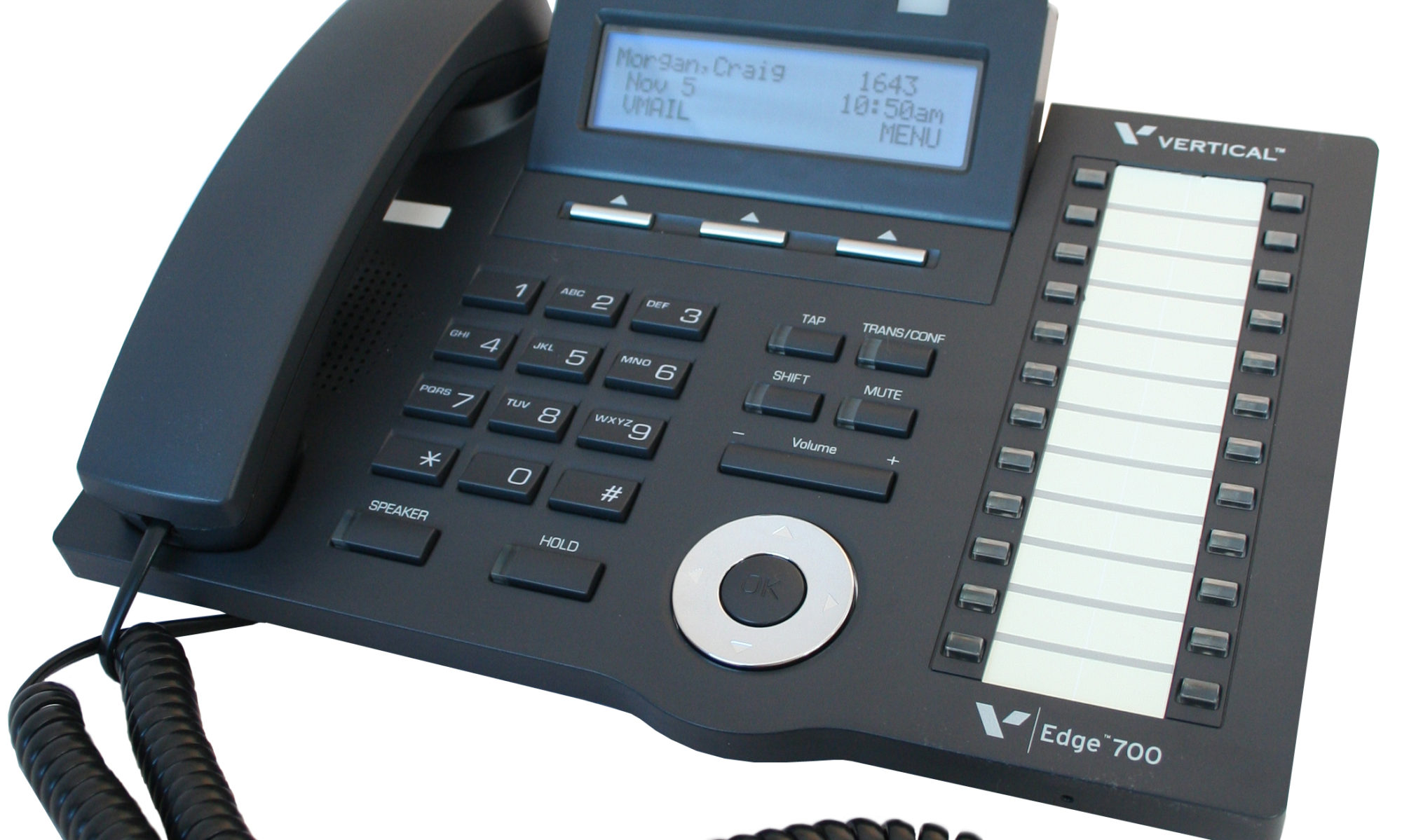
SBX IP 320 Phone User Guide (v2.0) – a “hard-copy” booklet supplied with digital phones
SBX 8-button Phone QRC (v2.0) }
SBX 24-button Phone QRC (v2.0) } – downloadable two-page quick-reference guides
SBX Voice Mail In-skin QRC (v2.5) }
Associated Windows-based Applications
PC Admin – the primary tool for programming and administering SBX IP 320 systems
PC Admin Offline Editor – offline version database editing tool
Speed Editor – a tool for managing system speed dials
ez Phone – a CTI application for SBX phone users
Nomad SP Soft Phone – PC-version of the IP remote phone
(There is a supporting document for each of the above applications on our website.) Vertical SBX IP 320
Issue 2.1 December 2008
General Information 1-2
Chapter 1: Basic System Features
SBX IP 320 Programming & Operations Guide
About This Guide
This manual is designed to provide information regarding SBX IP 320 general system feature
operation. In most cases, each feature described will contain three sections in the following Vertical SBX IP 320
order:
• CONDITIONS: explains any requirements or constraints of the feature related to its
configuration.
• ADMIN PROGRAMMING: provides information about configuring the feature using a
digital phone.
• OPERATION / SETUP: describes how to use and/or set up the feature using a digital
phone.
Programming Guidelines
The SBX IP 320 System can be programmed to meet each customer’s individual needs. The Vertical SBX IP 320
elements of Basic Admin Pre-programming are covered in the SBX IP 320 Installation Guide,
and can help to ensure you are prepared for Admin Programming of your SBX IP 320 System.
PC Admin Only
You must use the PC Admin application to set the following IP parameters which are located in
the VoIP appendix:
PGM 386 – IP Phone Atrributes (MAC address) … see page B-10
PGM 500 – SIP Attributes I … see page B-14
PGM 501 – SIP Attributes II … see page B-14
Pre-Programming
Pre-programming for the following should have been done immediately following Installation of
the SBX IP 320 System. For details, refer to Chapter 6 “Starting the SBX IP 320” in the SBX IP
320 Installation Guide.
1 – Site Name (PGM 100)
2 – Default System Setup by resetting the SBX IP 320 (a reset causes PGM 113 – Btn 14
to be set to ON, and PGM 181 to be set to 20 secs.)
3 – Numbering Plans Vertical SBX IP 320
4 – System IP Settings
Issue 2.1 December 2008
General Information 1-3
Chapter 1: Basic System Features
SBX IP 320 Programming & Operations Guide
Programming Using the Keyset
All programming is done at one station (Station 100, Station Port #00, by default) using the
4024-00 Digital Key Telephone (DKT).
Additional programming stations may be assigned, but only one DKT can be active in the
programming mode at any one time.
Programming Mode — when in programming mode, Station 100 does not operate as a normal
telephone, but instead works as a programming instrument with all of the buttons redefined.
The keys of the dial pad are used to enter the various data fields to enter numerical information.
Flexible Buttons — the 24 buttons located on the right side of the phone are used to indicate a
specific data field and to enter information.
Soft Buttons — the 3 functional soft buttons are used to go BACK to a previous menu, to Vertical SBX IP 320
DELETE data, or to SAVE data input.
Entering Programming Mode
To assign an Admin Password:
To enter programming mode:
1. Lift the Handset or press the speaker button on the Admin station.
The ICM dial tone will sound.
2. Press the [TRANS/PGM] button and dial * #.
A confirmation tone will sound.
3. Enter the Admin password, if a password has been set; a confirmation tone sounds
indicating that the Station is in Admin Programming mode.
Admin (DKTU only) — if value is set to
ON, the assigned station users can
program the Admin Database.
PGM 113 + FLEX 1 + 0
(Disable) + [HOLD/SAVE]
VALUES —
0 = Disable (default)
1 = Enable
(Default = Enable for Admin Vertical SBX IP 320
Station at station port 1 only)
Admin Password — an Admin password can be
assigned for entering Admin Programming
mode, as a security measure. To delete the
Admin password, press the [SPEED] button.
PGM 162 + Password (4
digits – *, #, 0-9) +
[HOLD/SAVE] Vertical SBX IP 320
VALUES —
Default = not assigned
# = ignore received digit
* = bypass the digit Vertical SBX IP 320
Issue 2.1 December 2008
General Information 1-4
Chapter 1: Basic System Features
SBX IP 320 Programming & Operations Guide
By default, there is no password.
4. Each program is accessed by pressing the [TRANS/PGM] button The following will
initially display:
5. Dial the desired three-digit program number. If an error is made while entering data,
the [TRANS/PGM] button will return to the previous status.
NOTE: To return to the previous state while in Admin Programming, press the [BACK] soft Vertical SBX IP 320
button to clear the temporary data fields.
Entering Ranges for Stations, COs, & Groups
The following Table is frequently used in Admin Programming procedures. When entering each
range, refer to the table, as the range is not always mentioned in the procedures. When entering
a programming area that involves stations or CO lines, you are prompted to enter the range of
stations or CO lines that you want to modify. To modify a single station or CO line, enter the
same number twice, e.g., 100100 = Sta 100 only, 01-01 CO line 1 only.
Saving System Changes
To accept changes while programming:
1. Press the [HOLD/SAVE] button when all changes have been entered to store the data
permanently.
2. A confirmation tone sounds when pressing the [HOLD/SAVE] button, if all data was
entered correctly. If there were any errors in the entering of data, an error tone will be Vertical SBX IP 320
presented and data will not be stored in the permanent memory.
Resetting the System
To reset the System:
Enter [PGM] + 450 then [FLEX] + 15 and press the [HOLD/SAVE] button.
ADMIN PROGRAM START
BACK DELETE SAVE Vertical SBX IP 320
ENTER PGM NUMBER
BACK DELETE SAVE
STATION RANGE CO RANGE CO LINE GROUP RANGE
100-131 01-12 01-24
Issue 2.1 December 2008
911 Feature 1-5
Chapter 1: Basic System Features
SBX IP 320 Programming & Operations Guide
911 Feature
The 911 feature was designed to give users one-button access to this emergency number. Any
phone can be programmed with a Flex button designated specifically for 911 calls. When using
this button, and all lines are busy, an active call is dropped so the 911 call can be placed.
IMPORTANT: A 911 button can be configured so that an access code (such as 9) is not required
before the 911 is dialed.
Also, any station user who programs a flex button for 911 ALERT will be notified whenever an
internal station places a 911 call. The system can store the last sixteen 911 calls placed, as well
as associated call information (e.g., time/date of call, and station no. where call was placed).
The initial 911 Alert indications include:
• Audible ringing tone
• Green flashing 911 ALERT flex button LED
• Automatic LCD display of 911 call information
CONDITIONS
• Based on the trunk access code assigned by the System Administrator, a station user can
place an emergency call in one of two ways:
– if the trunk access code is 9 by default, a station must dial 9 + 911.
– if the trunk access code is other than 9, a station can dial 911.
• If all trunks are busy, the system will drop an in-progress trunk, wait 1.5 seconds, and then
dial the 911 call.
ADMIN PROGRAMMING
OPERATION / SETUP
To place an emergency call:
Dial 9 + 911, or, 911 (see CONDITIONS).
To assign a 911 feature button for Alert: Vertical SBX IP 320
Press [TRANS/PGM] + 7 + #.
E911 Usage — if value is set to ON, the
designated CO Line is active for E911 use.
PGM 141 + FLEX 11 +
(Value)
VALUES —
0 = Off
1 = On
Default: CO Line 01 is set to ON;
all other CO Lines are set to OFF.
Issue 2.1 December 2008 Vertical SBX IP 320
Attendant Service 1-6
Chapter 1: Basic System Features
SBX IP 320 Programming & Operations Guide
Attendant Service
An Attendant can be configured to control the incoming calls by answering and transferring
calls, etc. There are two types of Attendants available for configuration within the system. One
Attendant can change simple settings of the whole system; the other provides programming for
intercom tenancy groups (LCD date/time format, etc.):
Main Attendant — a maximum of five stations can be defined as Main Attendants. These
Attendants control and effect the whole system. The “first” main Attendant is called the
“System” Attendant.
System Attendant — the System Attendant differs from the Main Attendant in regard to call
handling and system management priority. The System Attendant has more priority than
the Main Attendant(s); the System Attendant default is: Station 100.
NOTE: The System Attendant can be changed, but it cannot be removed. To change the
System Attendant, enter PGM 164 + FLEX 1 + Sta No. + [HOLD/SAVE].
Intercom Tenancy Group Attendant — each intercom tenancy group can have its own
Attendant. The Intercom Tenancy Group Attendant controls stations belonging to a Vertical SBX IP 320
specific intercom tenancy group. Intercom Tenancy Group Attendants affect only the
intercom tenancy group to which they belong.
NOTE: Generally, the Attendant of a station is the Intercom Tenancy Group Attendant to
which the station belongs. However, if an Intercom Tenancy Group Attendant of a
station doesn’t exist, the Main Attendant will provide the station with Atd services.
Assigning an Attendant
CONDITIONS
• An IP phone cannot be assigned as an Attendant.
ADMIN PROGRAMMING
Assign a Main Attendant
Assign an Intercom Tenancy Group Attendant
Main Attendants Assignment — Main Attendants
generally serve as call handlers. NOTE: To delete a
Main Attendant, press the FLEX button, and select
Attendant to delete; then press [SPEED] button.
PGM 164 + FLEX 2 +
Sta No. + [HOLD/SAVE]
VALUES —
Default = not assigned
Range = FLEX 2- 5
ICM Tenancy Group Attendant Assign — each Intercom
Tenancy group may have one attendant. Day / Night Mode
for Intercom Tenancy Groups is set by the Intercom
Tenancy Group Attendant.
PGM 120 + FLEX 1 +
ICM Tenancy Group Atd
(Attendant) + [HOLD/SAVE]
VALUES —
Sta No.
Issue 2.1 December 2008
Attendant Service 1-7
Chapter 1: Basic System Features
SBX IP 320 Programming & Operations Guide
Attendant Call & Queuing
CONDITIONS Vertical SBX IP 320
• If an Attendant calls another busy Attendant, the calling Attendant will hear a busy tone,
and can then Camp-On to the called (but busy) Attendant.
• If an Attendant activates unconditional Call Forward, the calls to that Attendant will follow
the configured call forward process.
• If a user dials 0 (zero), it will ring the Assigned Attendant station of the intercom tenancy
group to which the station belongs. If there is no station configured as an Assigned
Attendant, the call will ring the Main Attendant station.
• Call to any Attendant will be queued, if the Attendant is busy. Then, ring-back tone or MOH
will be provided to the calling party (see page 1-73).
ADMIN PROGRAMMING Vertical SBX IP 320
Assign a Main Attendant
Use PGM 164 … see page 1-6
Set the MOH Type
Use PGM 171 + FLEX 2 … see page 1-73
Assign the Intercom Group Attendant
Use PGM 120 + FLEX 1 … see page 1-6
Set Attendant Call Queuing (Ring Back Tone/Music On Hold) RBT/MOH
OPERATION / SETUP
To call an Attendant:
1. Go off-hook.
2. Press 0 (zero).
-orDial the station number of the Attendant.
Attendant Call Queuing Ring Back Tone — if value is set to RBT, ring
back tone is provided to the Station when the Station calls a busy
Attendant; otherwise, the hold tone or VMIB-MOH is provided (PGM
171 – FLEX 2).
PGM 160 + FLEX 1 Vertical SBX IP 320
+ 0 (MOH) +
[HOLD/SAVE]
VALUES —
0 = MOH
1 = RBT
Issue 2.1 December 2008
Attendant Service 1-8
Chapter 1: Basic System Features
SBX IP 320 Programming & Operations Guide
Attendant Forward
The Attendant can forward (Unconditional Call Forward) a call to another station. The
Forwarded-to station will temporarily substitute for the Attendant while the Attendant is in the
forwarded state.
CONDITIONS
• If the Attendant assigns Unconditional Call Forward to a Single Line Telephone (SLT) or
Wireless Handset Telephone Unit (WHTU), the Forwarded-to station only serves incoming
calls as an Attendant call or Attendant recall.
• Attendant features cannot be activated when forward is set to an SLT or WHTU.
OPERATION / SETUP
To activate Attendant Forward:
1. Go off-hook.
2. Press [DND/FWD].
3. Press 1 (for Unconditional Call Forward).
4. Dial the station number.
5. Hang up the handset. Vertical SBX IP 320
To deactivate Attendant Forward:
In an idle state, press [DND/FWD].
-orIn an off-hook state, press [DND/FWD], then #.
Attendant Intrusion
When an Attendant has an urgent message for a station already on a call on a CO line, the
Attendant can break-into the call to deliver the message to the designated station and the
distant party.
IMPORTANT: An ATD INTRUSION flex button must be programmed before this operation can
be performed. See “Flex Buttons” on page 1-52.
CONDITIONS
• To use this feature, the Auto Privacy should be set to OFF, and Override Privilege of the
Attendant should be ENABLED – see ADMIN PROGRAMMING.
• Also see “Emergency Intrusion” on page 1-49 and “Forced Trunk Disconnect” on
page 1-56 .
Issue 2.1 December 2008
Attendant Service 1-9
Chapter 1: Basic System Features
SBX IP 320 Programming & Operations Guide
ADMIN PROGRAMMING
Set Auto Privacy
PGM 161 + FLEX 5 … see page 1-34.
Set Privacy Warning Tone
PGM 161 + FLEX 6 … see page 1-34.
Set Override Privilege
PGM 113 + FLEX 4 … see page 1-34.
OPERATION / SETUP
To intrude on a CO call:
1. At the busy tone, press the programmed {ATD INTRUSION} button.
2. After the intrusion tone, converse with the station and/or the CO party.
To assign an {ATD INTRUSION} Flex button:
1. Press [TRANS/PGM], then press the Flex button to be assigned
2. Press [TRANS/PGM], then enter 86.
3. Press [HOLD/SAVE] to store the setting.
Attendant Override
A station in Do Not Disturb (DND) mode generally cannot receive incoming calls – see Vertical SBX IP 320
“Attendant Intrusion” on page 1-8 and “Barge In” on page 1-34.
The Attendant, however, can temporarily invalidate a station’s DND mode in order to call (and
transfer calls) to that station. In addition, the Camp-On feature can be used to override DND.
CONDITIONS
• The Attendant can only override a station’s DND mode (to transfer a CO call) if the station
has a CO or LOOP button (refer to the SBX IP 320 Programming Manual for more
information about CO and LOOP buttons.
• If target station has no CO or CO button, CO call will be recalled to Attendant immediately.
Issue 2.1 December 2008
Attendant Service 1-10
Chapter 1: Basic System Features
SBX IP 320 Programming & Operations Guide
OPERATION / SETUP
To override a DND state at a station:
When a DND tone is heard, press *, or the last digit of the dialed station number.
-orPress the programmed Camp-On Flex button. (See “Camp-on” on page 1-38.)
The DND warning tone will be changed to the Intercom ring-back tone at the
Attendant Station. The Attendant can then call a station in the DND state.
To assign the {Camp-On} Flex button:
1. Press [TRANS/PGM], then press the Flex button to be assigned.
2. Press [TRANS/PGM], then enter 85; press [HOLD/SAVE] to store the setting.
Attendant Recall Vertical SBX IP 320
If the recalled CO call (in the transfer or hold state) is unanswered by the destination station,
the CO call will be directed to the Attendant. The Attendant will receive the Recall ring as per
the setting of the Attendant Recall Timer.
CONDITIONS
• If the Attendant doesn’t answer the CO call for a time equal to the Attendant Recall Timer,
the CO call will be disconnected.
• If an Attendant for an Intercom Tenancy Group is not assigned, the CO call is recalled to
the System Attendant.
• When a call in Exclusive Hold is recalled to the Attendant, the call is placed on System
Hold. (See “Hold” on page 1-184.)
• A Private CO line will not be recalled to the Attendant.
ADMIN PROGRAMMING
Set Attendant Recall Timer
Set Hold Recall Timer
Attendant Recall Timer — if a recalled call arrives at the
Attendant station, and the Attendant does not answer within
the designated time, the system will disconnect the call.
PGM 180 + FLEX 1 +
01 (2 digits) +
[HOLD/SAVE]
VALUES —
Range = 00-60
minutes
I-Hold Recall Timer — when a recalled call is not answered,
it will recall to the Attendant after the designated time
expires. Vertical SBX IP 320
PGM 180 + FLEX 5 +
030 (3 digits) +
[HOLD/SAVE]
VALUES —
Range = 000-300
seconds
Issue 2.1 December 2008
Attendant Service 1-11
Chapter 1: Basic System Features
SBX IP 320 Programming & Operations Guide
LCD Date/Time Display
The Attendant can change the LCD Date/Time display format for stations in the system. There
are two date and two time format options:
• Date Format Options: MM-DD-YY or DD-MM-YY
Example: May 31, 2008 in MM-DD-YY format is 05-31-08, for DD-MM-YY format is 31-08-08.
• Time Format Options: 12H or 24H
Example: 8:30 P.M. in 12-hour format is 08:30 PM, in 24-hour format it is 20:30.
ADMIN PROGRAMMING
Set LCD Time/Date/Language Display Mode
OPERATION / SETUP
To toggle between the Date formats:
Press [TRANS/PGM], then 044.
To toggle between the Time formats:
Press [TRANS/PGM], then 045. Vertical SBX IP 320
LCD Time Display Mode — two LCD Time formats
are available: ordinary (12-hour), and military
(24-hour) mode.
PGM 169 + FLEX 1 + 1 (12H) +
[HOLD/SAVE]
VALUES —
0 = 24-Hour Mode
1 = 12-Hour Mode
LCD Date Display Mode — two LCD date formats
are available: Day/Month/Year or
Month/Day/Year mode.
PGM 169 + FLEX 2 + 1
(MMDDYY) + [HOLD/SAVE]
VALUES —
0 = DDMMYY
1 = MMDDYY
LCD Language Display Mode — a choice of 16
LCD language formats can be selected.
PGM 169 + FLEX 3 + VALUE Vertical SBX IP 320
(Range 00-15) + [HOLD/SAVE]
VALUES —
00 = English
01 = Italian
02 = Finnish
03 = Dutch
04 = Swedish
05 = Danish
06 = Norwegian
07 = Hebrew
08 = Germany
09 = French
10 = Portuguese
11 = Spanish
12 = Korean
13 = Estonia
14 = Russian
15 = Turkish
Issue 2.1 December 2008
Attendant Service 1-12
Chapter 1: Basic System Features
SBX IP 320 Programming & Operations Guide
Day/Night Service
CO call destinations can be changed according to the time of day. This means that if a call
comes in at 8:00am, it might go to a live Operator, while if it comes in at 8:00pm it might go to
the group or person covering evening calls. In addition, calls coming in during non-business
hours, weekend, or holidays, can be sent to the Auto Attendant, etc.
There are six ring modes: Day / Night / Weekend / On-Demand / Automatic Ring / Lunch
NOTE: According to ATD ring mode setting, Lunch Mode can be applied in DISA service, Ring Assigned
incoming call, DID service (see ADMIN PROGRAMMING).
CONDITIONS
• The destination of a CO call can be set differently for each ring mode. Vertical SBX IP 320
• Only an Attendant can change the ring mode. However, a user can use ADMIN
PROGRAMMING to set the destination of CO call.
• Any attendant can change the Ring Mode of an Intercom Tenancy Group. However, when
an Attendant of an Intercom Tenancy Group changes the ring mode, only the ring mode of
the Intercom Tenancy Group to which the Attendant belongs is changed. If a Main
Attendant changes the ring mode, the ring mode of the entire system will be changed.
• The Automatic Ring mode can be set as Day mode, Night mode, Weekend mode
according to the Weekly Time Table (see above).
• The On-Demand mode is used to supply a different destination of CO call, except Day
mode, Night mode, or Weekend mode. In addition, it is not available for us as the
Automatic Ring mode.
• When the ring mode is set to Automatic Ring mode by the Main Attendant, the ring mode
of the system will follow the first table entry (entry number: 00) of the Weekly Time Table.
• If the system ring mode is changed from the Night/Weekend/On-Demand/Auto Ring mode
to Day mode, the Ring mode of all Intercom Tenancy Groups will change to the previous
ring mode.
• There is no default assigned to the Lunch Mode.
• In PGM 144, Weekend mode, Lunch mode, or On-Demand mode, if a station is assigned
as the Ring destination, the only available Ring Delay Count is 0.
IMPORTANT: There cannot be two modes in Weekly Time Table set for the same time (for
example, Day Start Time and Lunch Start Time are the same). If this occurs, the
modes set cannot work properly.
Issue 2.1 December 2008
Attendant Service 1-13
Chapter 1: Basic System Features
SBX IP 320 Programming & Operations Guide
ADMIN PROGRAMMING Vertical SBX IP 320
Set the DISA Attribute
Use PGM 140 … see page 1-128
Set CO Line Ring Assignment
When CO Service Type (PGM 140) is set to Normal, incoming CO calls are routed
according to the destination assignment. The destination can be a station, Hunt Group,
VMIB announcement, Net-Station, or VM station number. The Ring Assignment is applied
separately to the Day/Night/Weekend/Lunch/On-Demand Ring Mode using FLEX 1-5.
Access Flexible DID Table
Use PGM 231 … see page 1-125.
Access Weekly Time Table
The Weekly Time Table can manage ring mode changes automatically. The use of the WEEKLY
TIME TABLE is executed by the System Attendant and each Intercom Tenancy Group
Attendant. The first table is for the System Attendant, and the others are for the Intercom
Tenancy Group Attendant.The table consists of 7 days – Monday, Tuesday, Wednesday,
Thursday, Friday, Saturday, & Sunday. On each day, the time zone of DAY/NIGHT/WEEKEND
mode can be programmed.
Ring Assignment — used to set the Ring
Assignment to a Station, Hunt Group, VMIB
Announce, Net-Station, or Auto Fwd to VM.
– To assign a call to a station, the delay value
must be entered. If delay value is set, the call
will begin to ring after delay time has expired.
– To receive incoming calls instantly, delay
value should be set to 0. (Attendant Station
100 is assigned with delay of 0.)
– To delete a programmed CO ring
assignment, press the [SPEED] button instead
of entering a delay value.
PGM 144 + FLEX
1-5 + Destination Vertical SBX IP 320
Type (1-5) + number
or range (based on
destination type) +
[HOLD/SAVE].
VALUES —
FLEX 1 = Day
FLEX 2 = Night
FLEX 3 = Weekend
FLEX 4 = Lunch
FLEX 5 = On-demand
Destination Type:
1 = Station Range + Delay (0-9)
2 = Hunt Group (620-629)
3 = VMIB (VMID MSG # 00-70)
4 = Net-Sta #
5 = Auto Fwd to VM (VM Sta #)
CO Ring Assignment Display — used to check
ring assignment destination of a CO line for
each Day/Night Ring Mode.
– If CO Calls are assigned to the station during
Day or Night Mode, the delay value can be
viewed (ex., value 100(1) means station 100
will receive a ring with a delay value of 1).
PGM 145 + FLEX 1 VALUES —
FLEX 1 = Day
FLEX 2 = Night
FLEX 3 = Weekend
FLEX 4 = Lunch
FLEX 5 = On-demand
Issue 2.1 December 2008
Attendant Service 1-14
Chapter 1: Basic System Features
SBX IP 320 Programming & Operations Guide
For example, the office work starts at 9:00 a.m. and finishes at 5:00 p.m.during week days. The
weekend starts at 5:00 p.m. from Friday to Sunday. In this case, the WEEKLY TIME TABLE can
be set as shown:
OPERATION / SETUP
To change the Day/Night Service mode:
1. At the Attendant Station, press [DND/FWD], then select a ring mode (1 through 6).
2. Press [TRANS/PGM], then press 074.
3. Press [HOLD/SAVE] to activate ring mode.
NOTE: Time can be set for each mode automatically using the Weekly Time Table. Vertical SBX IP 320
SAMPLE WEEKLY TIME TABLE
WEEKLY TBL: MON
D:09:00 N:17:00 W:
WEEKLY TBL: TUE
D:09:00 N:17:00 W:
WEEKLY TBL: WED
D:09:00 N:17:00 W:
WEEKLY TBL: THU
D:09:00 N:17:00 W:
WEEKLY TBL: FRI
D:09:00 N: W:17:00
WEEKLY TBL: SAT
D: N: W:00:00
WEEKLY TBL: SUN
D: N: W:00:00
Weekly Time Table — this table is
executed by the System
Attendant and each Intercom
Tenancy Group Attendant.
Time zone of
DAY/NIGHT/WEEKEND for 7
days is programmed.
PGM 233 + VALUE (Weekly
Time table, Range = 0-5) +
FLEX 1 (Day Mode, Range =
FLEX 1 – FLEX 7) + FLEX 1
(Day Start, Night Start,
Weekend Start, Lunch Start,
Lunch End, Range = FLEX
1-FLEX 5) + Enter Time
(HH/MM) + [HOLD/SAVE]
VALUES —
– Weekly Time Table (0-5)
– FLEX 1 (Day Mode F1-7)
F1 Monday Vertical SBX IP 320
F2 Tuesday
F3 Wednesday
F4 Thursday
F5 Friday
F6 Saturday
F7 Sunday
– FLEX 1 (Start/End Time – HH/MM)
F1 – Day Start
F2 – Night Start
F3 – Weekend Start
F4 – Lunch Start
F5 – Lunch End
Issue 2.1 December 2008
Attendant Service 1-15
Chapter 1: Basic System Features
SBX IP 320 Programming & Operations Guide
To change the time of a Day/Night Service mode:
Press PGM 233, then enter the times as needed.
NOTE: The default values of the Weekly Times are shown below. The first time settings
are for the Main Attendant (entry 00). Intercom Tenancy Group Attendants time
settings follow the Main Attendant (entry 01-15).
Outgoing Access
The Attendant can take a particular CO line out of service. If this occurs, outgoing CO cannot
be made while incoming CO calls are not affected.
CONDITIONS
• Any Attendant can use this feature.
• The LED of the CO line Flex button which is with an “out” setting, flashes at the Attendant
station, but is solidly lit at other stations.
• If a specific CO line is busy, it can still be taken out of service. The change in setting will
take effect after the CO line returns to an idle state.
OPERATION / SETUP
To set the CO line outgoing service:
1. Press [TRANS/PGM], then press 073.
2. Press the appropriate CO line Flex button.
A confirmation tone will sound when the status of the selected CO line is changed. Vertical SBX IP 320
3. Press [SPEAKER] to finish.
To release the”out” setting:
Press the flashing CO line Flex button at the Attendant station.
DATE DAY
START TIME
LUNCH
START TIME
LUNCH
END TIME
NIGHT
START TIME
WEEKEND
START TIME
Mon 09:00 -:- -:- 18:00 -:-
Tues 09:00 -:- -:- 18:00 -:-
Wed 09:00 -:- -:- 18:00 -:-
Thurs 09:00 -:- -:- 18:00 -:-
Fri 09:00 -:- -:- -:- 18:00
Sat -:- -:- -:- -:- 00:00
Sun -:- -:- -:- -:- 00:00
Issue 2.1 December 2008
Attendant Service 1-16
Chapter 1: Basic System Features
SBX IP 320 Programming & Operations Guide
DSS/BLF Consoles
Attendant stations and other digital phones may be equipped with DSS/BLF consoles which
provide additional buttons for additional operation. The consoles are arranged as flexible
mapped units. They are initially assigned with programming as one of 3 maps. All buttons of all
maps are programmable.
The DSS/BLF consoles each require a separate line connection to the KSU, and take up a
station number.
CONDITIONS
• There is no limit to the number of DSS/BLF consoles in a system.
• The default value for DSS/BLF is as follows:
Map 1 Flex 1 – Intrusion
Flex 2 – All Call Page
Flex 3 – Call Park 01
Flex 4 – Station Group 1
Flex 5 – Camp-on
Flex 6 – Internal All Call Page
Flex 7 – no default Vertical SBX IP 320
Flex 8 – no default
Flex 9 – no default
Flex 10 – no default
Flex 11 – no default
Flex 12 – no default
Stations 100-135
Map 2 Stations 136-147
Map 3 Empty
Issue 2.1 December 2008
Attendant Service 1-17
Chapter 1: Basic System Features
SBX IP 320 Programming & Operations Guide
ADMIN PROGRAMMING
Set Station ID Assignment
Set DSS/BLF ID Assignment
ICM Box Music
An Attendant can select the music channel source that provides music to the intercom Box /
Doorbox.
NOTE: Also see “Background Music (BGM)” on page 1-35, and “Music On Hold (MOH)” on page 1-73.
ADMIN PROGRAMMING
Enable Intercom Box Music Channel
Station ID Assignment — Station ID can be changed
to the desired value which is different from the
default value (e.g., normal DKTU /normal SLT).
This identifies the type of telephone (digital, SLT
Doorbox/ICM Box) attached to the system.
PGM 110 + FLEX 1 +
(Station ID value) +
[HOLD/SAVE]
VALUES —
01 = DKTU
05 = ICM BOX
06 = Reserved
07 = SLT (DTMF)
08 = SLT (PULSE)
09 = Reserved
10 = Reserved
11 = Reserved
12 = SLT – CID (FSK)
13 = SLT – CID (DTMF)
14 = IP Phone
DSS — one station can have up to 3 sequentially
numbered multiple DSS maps.
PGM 110 + FLEX 2 + (Station
ID value) + FLEX 2 + Station
Number + [HOLD/SAVE]
VALUES —
02 = DSS MAP 1
03 = DSS MAP 2
04 = DSS MAP 3
ICM Box / Doorbox Music Channel — establishes
which music channel will supply music to
Doorbox(es).
PGM 171 + FLEX 3 + 0
(VALUE) + [HOLD/SAVE]
VALUES —
0 = not assigned
1 = Int. Music
2 = External Music
3 = n/a
4-8 = SLT MOH
Issue 2.1 December 2008
Call Control 1-18
Chapter 1: Basic System Features
SBX IP 320 Programming & Operations Guide
OPERATION / SETUP
To select the music source from an Attendant Station:
1. Press [TRANS/PGM], then press 075.
2. Enter the music source/channel (00-12):
Channel 00: No music
Channel 01: Internal music
Channel 02: External music
Channel 03: VMIB BGM
Channel 04-08: SLT MOH
NOTE: As it is selected, the music source will be heard. However, if the music channel
has no music source, no music will be heard.
3. Press [HOLD/SAVE] to store the setting.
Station Feature Cancel
The Attendants can cancel features such as DND, Call Forward and pre-selected messages at
other stations. Vertical SBX IP 320
OPERATION / SETUP
To disable active features for a station from an Attendant Station:
1. Press [TRANS/PGM], press 071.
2. Enter the appropriate station range.
3. Press [HOLD/SAVE] to store the setting.
Call Control
Account Code
Account codes are used to identify outgoing (external) calls for accounting and billing purposes.
A separate account code can be assigned to each station (up to 12 digits: 0 to 11) so that a
company can identify and bill (where applicable) calls made from each station.
IMPORTANT: An ACCOUNT CODE flex button must be programmed before certain aspects of
this operation can be performed (see below).
Issue 2.1 December 2008
Call Control 1-19
Chapter 1: Basic System Features
SBX IP 320 Programming & Operations Guide
CONDITIONS
• Each station can be assigned its own account code.
• While entering the account code, the current call is put on hold.
• The user may enter the account code before or after a call conversation is established.
ADMIN PROGRAMMING
Set the SMDR Account Enter Code
Use PGM 106, then Flex 7. For more details, refer to the SBX IP 320 Installation Manual.
OPERATION / SETUP
To assign an ACCOUNT CODE flex button:
1. Press [TRANS/PGM].
2. Press the Flex button you want to assign as an ACCOUNT CODE button.
3. Press [TRANS/PGM], then press 80.
4. Press [HOLD/SAVE] to store the setting.
To enter an account code before accessing a CO line:
1. Press the programmed ACCOUNT CODE flex button.
2. Enter the account code (max of 12 digits), or press * button.
3. Intercom dial tone should be heard and a CO line is secured to make a call.
To enter an account code during a conversation:
1. While on a CO line call, press the ACCOUNT CODE flex button.
The other party will be put on hold.
2. Enter the account code (max of 12 digits).
3. Press the ACCOUNT CODE flex button.
You will be reconnected to the other party.
To enter an account code during a conversation (w/o using the ACCOUNT CODE flex button):
1. While on a CO line call, press [TRANS/PGM], then 550.
The other party will be put on hold.
2. Enter the account code (maximum 12 digits), or press * button.
You will be reconnected to the other party.
Issue 2.1 December 2008
Call Control 1-20
Chapter 1: Basic System Features
SBX IP 320 Programming & Operations Guide
Authorization Code
Authorization codes can be assigned to stations to give the users the ability to make calls on
restricted phone lines (overriding access restrictions). When a station is programmed to require
an Authorization Code, the assigned code must be entered in order to access a CO line.
CONDITIONS
• To prevent restricted, unauthorized phone calls from being made, personal authorization
codes should be kept secure by the System Attendant and individual station users.
• An authorization code must contain 3 to 11 digits.
• Each station must have a different authorization code. An authorization code cannot be
assigned to more than one station.
• Up to 200 authorization codes can be programmed on the system.
• If Loop LCR ACNT is set on a station, the authorization code is required each time the
station dials the Loop LCR CO Access code.
• An authorization code can be used for SMDR, DISA account codes.
• A long beep after a number is dialed indicates the need to enter an authorization code.
ADMIN PROGRAMMING
Access Authorization Code Table
Authorization code table entries consist of each station password and extra account
codes. The table entry from 001 to the maximum capacity of station numbers are saved
along with the password of each station. CO Line Groups can be marked to deny access
until a matched authorization code is entered. In this case, a DND warning tone is
provided when the CO Line Group access code is dialed.
There can be no duplicate entries. By default, Authorization Codes are not assigned. In an
SBX IP 320 system, the total number of Authorization Codes is 200 entries.
Authorization code length can be programmed as 5 digits or variable length (3-11digits). If
5-digit authorization code usage is programmed, the authorization code works as 5-digit Vertical SBX IP 320
length in admin program or features.
Issue 2.1 December 2008
Call Control 1-21
Chapter 1: Basic System Features
SBX IP 320 Programming & Operations Guide
Enter the appropriate Bin number (001-200), then follow the procedure as shown:
Set DISA Account Code
Use PGM 141 … see page 1-130.
Access CO Line Group Account
Set Loop LCR Account Code
Set 5 Digit Authorization Code Usage
Authorization Code Table — if the dialed
Authorization code is verified, a CO dial tone
will be presented. Otherwise, an error tone
will be heard and access to the group will be
denied. Stations or Admin programming can
enter authorization codes. The Administrator
can see and change station passwords-no
duplicate entries. The total number of
Authorization Codes is 200 entries.
PGM 227 + FLEX 1 +
Authorization Code (3-11
digits; Range = 0-9) +
[HOLD/SAVE]
VALUES —
Default = Not Assigned
Authorization codes can be
programmed as 5 digits or
flexible length (3-11 digits);
refer to PGM 161 – FLEX21
Day COS of Authorization Code — Day COS
of stations can only be viewed; COS for
extra entries can also be assigned.
PGM 227 + FLEX 2 +
Class of Service Value +
[HOLD/SAVE]
VALUES —
Range = 1-9
Night COS of Authorization Code — Night
COS of stations can only be viewed; Night
COS for extra entries can also be assigned.
PGM 227 + FLEX 3 +
Class of Service Value +
[HOLD/SAVE]
VALUES —
Range = 1-9
CO Line Group Account — if this value is set to ON, the CO Line
user will be prompted to enter an authorization code to access
this CO Line. Vertical SBX IP 320
PGM 141 + FLEX 9 + 0
(Off) + [HOLD/SAVE]
VALUES —
0 = OFF
1 – ON
Loop LCR Account Code — if value is set to ON, the Station
User must enter an Account Code to use Loop LCR.
PGM 111 + FLEX 16 + 0
(Off) + [HOLD/SAVE]
VALUES —
0 = OFF
1 = ON
5 Digits Authorization Code Usage — if value is set to ON,
Authorization code is programmed as 5 digits fixed length.
Under this mode, 5 digits of the authorization code should be
entered when related features are activated. If this value is set
to OFF, Variable Authorization code (3-11 digits) is used.
PGM 161 + FLEX 21 + 0
(Off) + [HOLD/SAVE]
VALUES —
0 = OFF
1 = ON
Issue 2.1 December 2008
Call Control 1-22
Chapter 1: Basic System Features
SBX IP 320 Programming & Operations Guide
Enable Station Account
OPERATION / SETUP
To access a CO line using an authorization code:
1. When a long warning tone sounds after dialing, enter the designated authorization
code.
2. Press # to complete the entry.
NOTE: If a five digit authorization code type (see ADMIN PROGRAMMING), you do
not need to press #. If the code entered is valid/correct, the CO line will be
connected. Otherwise, an error tone will be presented.
To register the authorization code on a station:
1. Press [TRANS/PGM], then 31.
2. Enter the authorization code, then press #.
NOTE: If a five digit authorization code type (see ADMIN PROGRAMMING), you do Vertical SBX IP 320
not need to press #.
3. Press [HOLD/SAVE] to store the changes.
To change the authorization code at a station:
1. Press [TRANS/PGM], then 32.
2. Enter the current authorization code.
3. Enter in the new authorization code.
4. Press [HOLD/SAVE] to store the change.
Automatic Call Release
When a station does not complete a connection on an outgoing CO line, or receives no answer
on an intercom call, the system will disconnect the call based on assigned Auto Release Timer.
CONDITIONS
• If a user station is in speaker mode, the Station returns to idle, otherwise the station will
receive an error tone if using the handset.
• An Intercom call in Hands-Free mode is answered, Station Auto Release will not be
activated.
Forced Station Account Code — if this value is set to ON, a
password is needed to access an outgoing CO line.
PGM 112 + FLEX 20 + 0
(Off) + [HOLD/SAVE]
VALUES —
0 = OFF
1 = ON
Issue 2.1 December 2008
Call Control 1-23
Chapter 1: Basic System Features
SBX IP 320 Programming & Operations Guide
• When the Automatic Release time is set to 0, the feature is not activated.
• If a call is dialed without lifting the handset, and the Auto Release timer expires, the call
will be canceled. In addition, the station will automatically return to an idle state.
• If a call is dialed using the handset, and the Auto Release timer expires, the call will be
canceled. An error tone will sound.
ADMIN PROGRAMMING
Set Automatic CO Release Timer
Set Station Auto Release Timer
Class Of Service (COS)
Each station and CO line may be assigned different classes to either allow or restrict call
service. The level of COS assignments are programmed at each station and each CO line.
CONDITIONS
COS Rules
• In STA COS 7, no dialing is allowed on CO lines.
• In CO COS 5, STA COS 1-6 is ignored, and there is no restriction on access to CO lines.
• CO COS 4, STA COS 1~6 are ignored, and long distance calls are not allowed; max. 8
digits may be dialed.
• CO COS 1 is restricted by the STA COS.
• CO COS 2 and STA COS 2/4 are restricted by Exception Table A.
• There is no restriction in STA COS 1/3.
• In STA COS 5, long distance calls are not allowed; max. 8 digits can be dialed.
CO lines Allow/Deny Restriction Rules
• If there are no entries, no restriction is provided by the table.
• If there are entries in the Deny table, then the restriction is on a Deny Only basis.
Automatic CO Release Timer — Uncompleted CO line
calls will automatically be released when the timer
expires.
PGM 180 + FLEX 14
+ 030 (seconds, 3 Vertical SBX IP 320
digits) + [HOLD/SAVE]
VALUES —
Range = 020-300
Station Auto Release Timer — If a station user hears a
ring back tone and no action is taken within the
designated time, the station will be released.
PGM 182 + FLEX 5 +
060 Value (10 msec, 3
digits) + [HOLD/SAVE]
VALUES —
Range = 020-300
Issue 2.1 December 2008
Call Control 1-24
Chapter 1: Basic System Features
SBX IP 320 Programming & Operations Guide
• If there are entries in the Allow table, then the restriction is on an Allow Only basis.
• If there are entries in both the Allow and Deny Tables, the Allow Table is searched first. If a
dialed number matches an entry in the Allow Table, the call is allowed. If a match is not
found, then the Deny Table is searched. If a match is found in the Deny Table, the number
is restricted. If no match is found in either table, the number is allowed.
General Rules
• PBX Access Codes: There are five (2-digit) PBX access codes that allow you to enter the
system and access a CO line via PBX. A CO line marked as a PBX line will not be
controlled by any station or CO line COS until a recognized PBX code is dialed.
• Canned Restrictions: Canned, Restricted1: Long distance call is not allowed (8 digits
maximum). Canned, Restricted2: Long distance call is not allowed (longer than 8 digits).
• Exception Tables A and B: These are the two exception tables for COS. Each table has 20
“allow” codes and 10 “deny” codes. Each code may have eight entries.
• CO Call Toll Checks: If an incoming CO Call Toll Check is set, the COS rule is applied
when the station dials after answering an incoming CO call.
CO LINE COS Vertical SBX IP 320
S
T
A
T
I
O
N
C
O
S
1234 5
1 Unrestricted Unrestricted Unrestricted Canned
Restricted
Unrestricted
2 Table A Table A Table B Canned
Restricted
Unrestricted
3 Table B Unrestricted Unrestricted Canned
Restricted
Unrestricted
4 Table A, B Table A Table B Canned
Restricted
Unrestricted
5 Canned
Restricted2
Canned
Restricted2
Canned
Restricted2
Canned
Restricted1
Unrestricted
6 Canned
Restricted1
Canned
Restricted1
Canned
Restricted1
Canned
Restricted1
Unrestricted
7 Intercom Only Intercom Only Intercom Only Intercom Only Intercom Only
8 Table C Table C Unrestricted Canned
Restricted1
Unrestricted
9 Table D Table D Unrestricted Canned
Restricted1
Unrestricted
Issue 2.1 December 2008
Call Control 1-25
Chapter 1: Basic System Features
SBX IP 320 Programming & Operations Guide
COS 1 There is no restriction to dial.
COS 2 Monitored by Exception Table A
COS 3 Monitored by Exception Table B
COS 4 Monitored by Exception Table A & B
COS 5 Long distance call is not allowed; longer than 8 digits
COS 6 Long distance call is not allowed; max. 8 digits may be dialed
COS 7 Only intercom, paging and emergency calls are allowed; no dialing allowed on CO lines
COS 8 Monitored by Exception Table C
COS 9 Monitored by Exception Table C
COS 1 There is no restriction. Monitored by STA COS.
COS 2 Monitored by Exception Table A & STA COS 2/4.
COS 3 Monitored by Exception Table B & STA COS 2/4
COS 4 Long distance call is not allowed for all STA COS;
max. 8 digits may be dialed
COS 5 Overrides STA COS 2, 3, 4, 5, 6, no COS restriction
COS 1 There is no restriction to dial
COS 2 Monitored by Exception Table A
COS 3 Monitored by Exception Table B
COS 4 Monitored by Exception Table A & B
COS 5 Long distance call is not allowed; longer than 8 digits
COS 6 Long distance call is not allowed; only max. 8 digits may be dialed
COS 7 Only intercom, paging and emergency call are allowed;
no dialing allowed on CO lines
COS 8 The assignments in the Exception Table C are monitored for allow and deny numbers
COS 9 The assignments in the Exception Table D are monitored for allow and deny numbers
Issue 2.1 December 2008
Call Control 1-26 Vertical SBX IP 320
Chapter 1: Basic System Features
SBX IP 320 Programming & Operations Guide
ADMIN PROGRAMMING
Set Station COS
Enter the appropriate station range, then follow the procedure as shown:
Set CO Line COS
Station COS — each station is assigned a Class Of
Service (COS) that determines the station toll
restriction for day and night operation (refer to Table).
On a particular call, the CO COS is combined with
Station COS to determine the restriction. COS for all
stations at day and night operation are 1 by default.
The weekend COS is the same as night COS.
PGM 116 + FLEX 1 (Day) +
1 (COS, Range = 1-9) +
[HOLD/SAVE]
PGM 116 + FLEX 2 (Night)
+ 1 (COS, Range = 1-9) +
[HOLD/SAVE]
VALUES —
FLEX 1 = Day
FLEX 2 = Night
STA COS DESCRIPTION
1 No restrictions are placed at the station for dialing.
2 The assignments in Exception Table A are monitored for Allow and Deny numbers.
3 The assignments in Exception Table B are monitored for Allow and Deny numbers.
4 The assignments in Exception Tables A & B are monitored for Allow and Deny numbers.
5 The leading digit dialed cannot be a long distance code. The dialed digits can be longer than
7 digits. There is no restriction for the number in the Canned Toll Table.
6 The leading digits cannot be a Long Distance code. Only eight digits maximum can be
dialed. (There is no restriction for the number in the Canned Toll Table.)
7 Intercom and paging calls are allowed. No dialing is allowed on CO lines. ICM boxes are
assigned with this COS.
8 The assignments in Exception Table C are monitored for allow and deny numbers.
9 The assignments in Exception Table D are monitored for allow and deny numbers.
CO COS — COS is assigned to each CO
line.
PGM 141 + FLEX 2 + 1
(COS) + [HOLD/SAVE]
VALUES —
1 = No restriction
2 = Exception Table A governs
3 = Exception Table B governs
4 = Restricts Long Distance Code
5 = Overrides Station COS 2-6
Issue 2.1 December 2008
Call Control 1-27
Chapter 1: Basic System Features
SBX IP 320 Programming & Operations Guide
Set CO-to-CO COS
Access Toll Exception Table
The Allow/Deny Tables are organized into 2 sets of tables to support 2 different toll plans at one
installed site. Each allow/deny table may contain up to 30 number strings. All bins of allow and
deny tables have no entries by default. Each number string can contain up to 14 entries Vertical SBX IP 320
including any number 0-9, *, #, “Don’t care.”
The following rules should be remembered when setting up the Allow/Deny Tables:
• If the tables have no entries, no restriction is applied.
• If entries are made in the allow table and only there, then only those numbers are allowed.
• If entries are made in the deny table and only there, then only those numbers are denied.
• If there are entries in both tables, the allow table is searched at first and if number is found,
it is allowed. If not found, the deny table is searched and if number is found, it is denied. If
it is not found in either table, it is allowed.
Day COS — Class-of-Service of Day Mode PGM 166 + FLEX 1 + 07
(VALUE) + [HOLD/SAVE]
VALUES —
01-11
Night/Weekend COS — Class-of-Service of Night/Weekend
Mode
PGM 166 + FLEX 2 + 07
(VALUE) + [HOLD/SAVE]
VALUES —
01-11
RULE ENTRY CONDITIONS & RESULT
ALLOW DENY ALLOW TABLE DENY TABLE
1 Not Exist Not Exist No Restriction No Restriction
2 Exist Not Exist Found – allowed
Not found – denied
—
3 Not Exist Exist — Found – denied
Not found – allowed
4 Exist Exist Found – allowed
Not found – check deny table
Found – denied
Not found – allowed
Issue 2.1 December 2008
Call Control 1-28
Chapter 1: Basic System Features
SBX IP 320 Programming & Operations Guide
Allow Table A – -used to check whether the dialed
digits by COS 2 and COS 4 station is matched with the
allowed toll pass digits. NOTE: Allow table A is only
used when the COS of dialed station is COS 2 or 4.
PGM 224 + FLEX 1 + VALUE
(refer to Allow Table) + Allow
Number (max 14 digits; 0-9,
#, *, Don’t Care) +
[HOLD/SAVE]
VALUES —
Range = 01-30
Deny Table A — used to check whether the dialed
digits by COS 2 and COS 4 station is matched with the
denied toll pass digits. NOTE: Deny table A is only
used when the COS of dialed station is COS 2 or 4.
PGM 224 + FLEX 2 + VALUE
(refer to Deny Table) + Deny
Number (Max 14 Digits; 0-9,
#, *) + [HOLD/SAVE]
VALUES —
Range = 01-30
Allow Table B — used to check whether the dialed
digits by COS 3 and COS 4 station is matched with the
allowed toll pass. NOTE: Allow table B is only used
when the COS of dialed station is COS 3 or 4.
PGM 224 + FLEX 3 + VALUE
(refer to Allow Table) + Allow
Number (Max 14 Digits; 0-9,
#, *) + [HOLD/SAVE]
VALUES —
Range = 01-30
Deny Table B — used to check whether the dialed
digits by COS 3 and COS 4 station is matched with the
denied toll pass digits. NOTE: Deny table B is only
used when the COS of dialed station is COS 3 or 4.
PGM 224 + FLEX 4 + VALUE
(refer to Deny Table) + Deny
Number (Max 14 Digits; 0-9,
#, *) + [HOLD/SAVE]
VALUES —
Range = 01-30 Vertical SBX IP 320
Allow Table C — used to check whether the dialed
digits by COS 8 station is matched with the allowed toll
pass digits. NOTE: Allow table A is only used when the
COS of dialed station is COS 8.
PGM 224 + FLEX 5 + VALUE
(refer to Allow Table) + Allow
Number (Max 14 Digits; 0-9,
#, *) + [HOLD/SAVE]
VALUES —
Range = 01-50
Deny Table C — used to check whether the dialed
digits by COS 8 station is matched with the denied toll
pass digits. NOTE: Deny table A is only used when the
COS of dialed station is COS 8.
PGM 224 + FLEX 6 + VALUE
(refer to Deny Table) + Deny
Number (Max 14 Digits; 0-9,
#, *) + [HOLD/SAVE]
VALUES —
Range = 01-50
Allow Table D — used to check whether the dialed
digits by COS 9 Station is matched with the allowed toll
pass.
NOTE: Allow table B is only used when the COS of
dialed station is COS 9.
PGM 224 + FLEX 7 + VALUE
(refer to Allow Table) + Allow
Number (Max 14 Digits; 0-9,
#, *) + [HOLD/SAVE]
VALUES —
Range = 01-50
Deny Table D — used to check whether the dialed
digits by COS 9 Station is matched with the denied toll
pass digits. NOTE: Deny table B is only used when the
COS of dialed station is COS 9.
PGM 224 + FLEX 8 + VALUE
(refer to Deny Table) + Deny
Number (Max 14 Digits; 0-9,
#, *) + [HOLD/SAVE]
VALUES —
Range = 01-50
If programming FLEX 1-4, you must reenter PGM 224 to gain access to programming of FLEX 5-8 and vice versa.
Issue 2.1 December 2008
Call Control 1-29
Chapter 1: Basic System Features
SBX IP 320 Programming & Operations Guide
Access Canned Toll Tables
In addition to the basic toll restrictions, stations within COS 5 or 6 are subject to dial restrictions
based on the Canned Allow and Deny Tables. This program permits entries in the Canned Toll
Tables. Both the Allow and Deny table have 20 bins up to 14 digits.
Enable Incoming Toll Check
System Speed Zone
System Speed Zones consist of Speed bins & stations. Toll checks based on COS can be
applied to zones. Up to 10 speed number zones can be defined. Only stations allocated to
zones can access these bins. Speed bins not allocated to zones can be accessed by all stations
and no toll checks are applied.
ADMIN PROGRAMMING
Enable Speed Dial Access
Use PGM 112, then FLEX 9 … see page 1-168.
Assign System Speed Zone
Use PGM 232 … see page 1-168.
VALID DATA FUNCTION LCD DISPLAY
0-9, *, # Number as dialed
[DND/FWD] Don’t Care “D”
Allow Table — used to check, whether the dialed
digits by COS 5 and COS 6 station is matched with
the allowed toll pass digits. NOTE: Allow table of
canned toll is only used when the COS of dialed
station is COS 5 or 6.
PGM 225 + FLEX 1 + VALUE
(refer to Allow Table) + Allow
Number (Max 14 Digits; 0-9, #, *)
+ [HOLD/SAVE]
VALUES —
Range = 01-20
Deny Table — used to check whether the dialed
digits by COS 5 and COS 6 station is matched with
the denied toll pass digits. NOTE: Deny table of
canned toll is only used when the COS of dialed
station is COS 5 or 6.
PGM 225 + FLEX 2 + VALUE
(refer to Deny Table) + Deny
Number (Max 14 Digits; 0-9, #, *)
+ [HOLD/SAVE]
VALUES —
Range = 01-20
Incoming Toll Check — if this value is set to ON, the system
checks for tolls applied to incoming CO calls.
PGM 161 + FLEX 16 + 0
(OFF) + [HOLD/SAVE]
VALUES — Vertical SBX IP 320
0 = Off
1 = On
Issue 2.1 December 2008
Call Control 1-30
Chapter 1: Basic System Features
SBX IP 320 Programming & Operations Guide
Enable CO Dial Tone Detect
Walking Class of Service (Walking COS)
This feature allows temporary override of the toll restriction to allow toll call from previously toll
restricted phones. The authorization code can be used as a verified account code for SMDR.
CONDITIONS
• This feature can be used on both digital and SLT phones.
• This feature is available on a per-use basis only. The original programmed station COS
will be used when activating Walking COS, disconnecting a call, or pressing
[TRANS/PGM] to hold the call (and seize another line).
• When a wrong number is dialed, press [FLASH] to dial again without having to access
another idle CO line.
• The fee for a call with Walking COS will be charged according to the station authorization
code, not the actual station.
• When a user tries to use Walking COS at a station set to COS 7 (with temporary COS),
the call will follow the original COS of the station.
ADMIN PROGRAMMING
Access the Authorization Code Table
Use PGM 227 … see page 1-20.
OPERATION / SETUP
To activate Walking COS:
1. Press [TRANS/PGM], then press 23.
A confirmation tone sounds.
2. Enter the authorization code; the intercom dial tone sounds and the used extension
COS is temporarily changed. (Note: A CO call can only be placed one time.)
To program a Walking COS flex button:
1. Press [TRANS/PGM], then the applicable Flex button.
2. Press [TRANS/PGM], then 23.
3. Press [HOLD/SAVE] to store the setting.
CO Dial-Tone Detect — when speed dial is activated, if this
value is set to ON, the system will detect a dial tone using CPT
instead of the pause timer.
PGM 160 + FLEX 6 + 0 Vertical SBX IP 320
(OFF) + [HOLD/SAVE]
VALUES —
0 = OFF
1 = ON
Issue 2.1 December 2008
Call Handling 1-31
Chapter 1: Basic System Features
SBX IP 320 Programming & Operations Guide
Call Handling
Alarm
This feature allows you to set up an external contact to create an internal alarm. When the
contact is established and programmed, an alarm tone (single tone repeated per 1-min. interval
or a continuous tone) can be sent to designated stations within the system.
NOTE: Refer to the SBX IP 320 Programming Manual for more information about this feature.
CONDITIONS
• An external contact should be connected to the alarm input.
• The alarm contacts should be dry (no voltage/current source connected).
• Single Line Telephones (SLTs) cannot receive alarm signals.
• An Alarm Reset can be programmed on a Flex button.
ADMIN PROGRAMMING
Enable Alarm
Set Alarm Contact Type
Select Alarm Mode
Alarm Enable — if value is set to ON, Alarm is available. PGM 163 + FLEX 1 + 0
(Off) + [HOLD/SAVE]
VALUES —
0 = Off
1 = On
Alarm Contact Type PGM 163 + FLEX 2 + 1
(Close) + [HOLD/SAVE]
VALUES —
0 = Open
1 = Close
Alarm Mode PGM 163 + FLEX 3 + 1
(Alarm) + [HOLD/SAVE]
VALUES —
0 = Door Bell
1 = Alarm
Issue 2.1 December 2008
Call Handling 1-32
Chapter 1: Basic System Features
SBX IP 320 Programming & Operations Guide
Select Alarm Signal Mode
OPERATION / SETUP
To terminate the alarm signal from an Attendant Station:
Press 565.
A confirmation tone sounds, and the alarm signal will be terminated at all assigned
stations.
Automatic Incoming Fax Transfer
The system automatically determines if an incoming call from the designated analog CO line is
for a fax or for a speech terminal by detecting the tone of the call (that is, 1100Hz, 0.5s ON/3s
OFF repeated). When the system detects a fax tone from the incoming line within the
predetermined time, the system transfers the call to the appropriate fax station. If the fax tone Vertical SBX IP 320
is not detected within the predetermined time, the system interprets this as a normal phone call
(no fax), so the call is transferred to the specified station.
IMPORTANT: Only analog lines are enabled for using this feature.
CONDITIONS
• Only one CO line can be designated as a fax CO line. If a fax CO line is not programmed,
Automatic Fax Transfer cannot be activated.
• Station 17 is pre-programed station for fax transfers. Therefore, the fax machine should be
connected to the port for Station 17.
• If the fax CO line is not answered within the fax CO call time, the incoming call will be
disconnected.
• An outside caller connected to the fax CO line will hear a ring back tone when the system
detects a fax tone.
• To transfer calls from the fax to a fax station, do not assign CO ring to the fax Station 17.
• If a CO line is programmed for DISA, as well as for Automatic Fax Transfer, incoming calls
from that CO line are served as DISA calls. Therefore, if a user wants to call the fax
station, they will need to call Station 17 via the DISA call.
• When the fax machine goes idle after a fax call, the associated CO line is released.
• If the fax CO line is disconnected during a fax call, the CO line is released, and the fax
machine returns to an idle state.
Alarm Signal Mode — if value is set to REPEAT, the Alarm
Signal is repeated until Alarm is reset.
PGM 163 + FLEX 4 + 1
(Repeat) + [HOLD/SAVE]
VALUES –
0 = Once
1 = Repeat
Issue 2.1 December 2008
Call Handling 1-33
Chapter 1: Basic System Features
SBX IP 320 Programming & Operations Guide
ADMIN PROGRAMMING
Set Auto Fax Transfer CO
Set Fax Tone Detect Timer
Set Fax CO Call Timer
Automatic Privacy
By default, all conversations (on CO lines, the intercom, and conferences) are protected by
privacy (Automatic privacy). This prevents one station from accessing a line to listen in on a
conversation. However, this feature can be disabled by the station user as needed (via the HTP
feature). To allow a user to have the ability to enable or disable Automatic Privacy, the System Vertical SBX IP 320
Attendant must make such a configuration in the system.
CONDITIONS
• If Automatic Privacy is enabled, a busy tone is heard when an attempt is made to access a
busy CO line.
• If Automatic Privacy is disabled, intruding station is connected to conversation in progress.
• When Automatic Privacy is disabled, privacy is still active for Intercom & Conference calls.
• A station can only override a privacy-disabled station.
• The station with Privacy disabled will hear an “intrustion” tone when another station
accesses the line.
Auto Fax Transfer CO — if an Auto FAX CO line is
programmed, the system answers and detects the FAX
calling tone (1100Hz, 0.5sec ON/3sec OFF repeat tone)
from an incoming analog CO line. The system will route
this call to the last SLT port on basic MBU when tone is
detected within the programmed time.
Legacy Business Telephone Systems:
Do you have a legacy telephone system and are looking for a new vendor? We are ready to serve!!! Our seasoned Technicians work on Vertical, Comdial, Nortel, Vodavi, Toshiba, AT&T, Avaya, Lucent, Panasonic, NEC and many others.
800-821-2686