
800-821-2686
614-420-4572
2783 Martin Rd.
Dublin, OH 43017
513-926-6186
9891 Montgomery, Rd.
Cincinnati, Ohio 45242
937-222-2269
2324 Stanley Avenue
Dayton, Ohio 45404
Local Technicians equal Great Service!!
800-821-2686
We have many “crash systems” and repair parts in stock to get your system up and operating the same day.
Our suppliers can provide us with almost any equipment including unusual and outdated brands. We can usually have your system operational by the next morning.
 Loading...
https://ohiotele.net/manuals/comdial/Comdial%20DXP%20Plus%20General%20Description.pdf
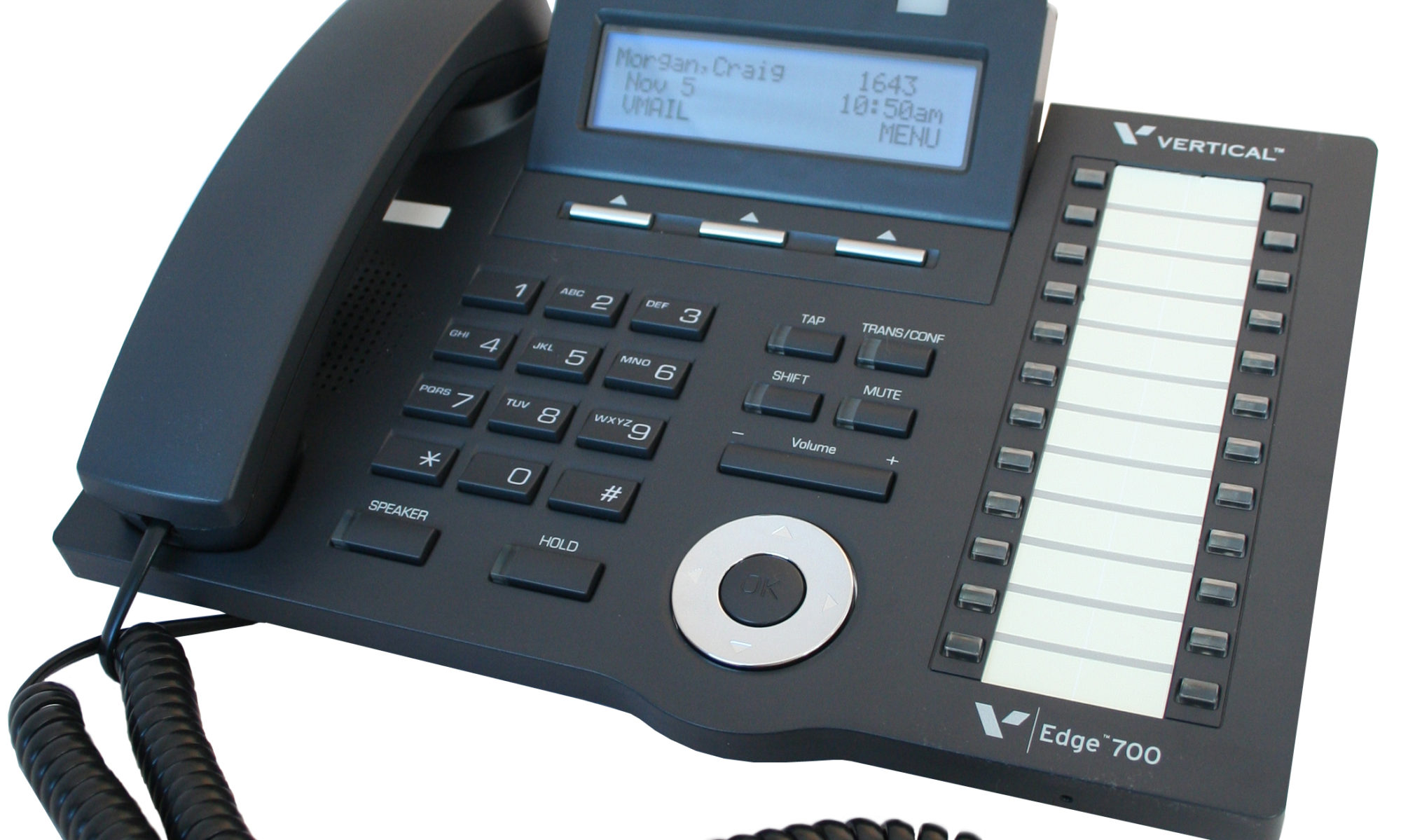
Our seasoned Technicians work on Vertical, Comdial, Nortel, Vodavi, Toshiba, AT&T, Avaya, Lucent, Panasonic, NEC and many others.
800-821-2686

The Comdial FX, FXT, FXS, MP5000 supports the following telephone features on both analog and digital proprietary telephones. Some of these features are system-wide and others are specific to individual stations.
Alphanumeric Display — Displays time, day and date — Keeps you apprised of the status of your telephone — Provides programming prompts Comdial DXP Plus
Auxiliary Jack (used only with
Impact
and DigiTech LCD speakerphone) — Allows you to use your telephone privately and handsfree with headset — Allows you to plug in a tape recorder — Allows you to plug in a loud ringer — Helps improve operation of high-volume business applications by adding a paging speaker
Button Query — Allows you to see the function of a programmed button on your LCD screen
Hold Button — Places a line on hold — Stores pauses in number sequences while programming — Allows you to scroll through multiple held calls on display
Interactive Buttons — Provide quick and easy access to system and call processing features — Provide straightforward button programming without dialing codes (the interactive buttons themselves, however, are not programmable) Comdial DXP Plus
Intercom Button — Selects an intercom line — Initiates many of the features of the telephone
Message Waiting Light
@BULLET TEXT 3 = Tells you that there is a message for you Comdial DXP Plus
Mute Button — Keeps the person on the line or speakerphone from hearing your conversation
Programmable Buttons — Allow you to program your telephone for automatic dialing functions — Allow you to program your telephone for Direct Station Selection (DSS) — Show which lines and intercoms are either in use or on hold — Allow you to store frequently used feature codes at unused buttons
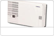
The basic system consists of a main cabinet, which accepts 14 printed-wire boards, and two expansion cabinets; the upper expansion cabinet accepts twelve printed-wire boards, and the lower cabinet accepts eleven (see Figure 7). Some of the printed-wire boards also hold smaller circuit cards that mount directly to the boards (See section 3.5 for card information) The line boards are listed in section 3.3; station boards are located in section 3.4. The complement of circuit boards include the following (for information on the main Comdial FX, FXT, FXS, MP5000 package, see section 3.6, Locating The Boards):
Auxiliary Board: — A utility board that provides interface for a maximum of four special-purpose circuit cards. Actual make-up requirements depend upon system configuration.
Central Processing Unit (CPU) Board: — Provides central processing and control for the system and other miscellaneous functions. The CPU board has the time switch and conference circuitry and two serial data ports, which have been dedicated for PC-based programming and a remote maintenance modem.
Conference Board: — Provide additional conference capability. Each board provides 5 additional 3-way conferences.
Interface Boards: — Ties the main cabinet to the expansion cabinet. Each expansion cabinet has an interface board; that connects the main cabinet with the expansion cabinets. Interface boards are included with the expansion cabinet packages.
Memory Card: — Provides the memory storage and operating system control. The card mounts directly onto the CPU board, and it is available with two (four megabyte as a future feature) of memory. The system uses re-programmable random access memory, known as “flash memory” or “flash RAM” —not replaceable memory chips, known as “EPROM”.
Services Board: — Provides an interface for music-on-hold and background music inputs; it also provides an output to an external paging amplifier. The services board includes four dry-contact relays for external control functions. You can also add up to three additional cards onto the services board for data communications, DTMF tone receiving, and E1 or T1 synchronization.
Because there are no dedicated station or line ports in the DXP Plus, the system uses an automatic configuration method to number the lines and stations. When you master clear the system, it automatically searches for all installed line and station boards in the main and expansion cabinets. Once the system has identified the board type and location, it automatically numbers the ports on every installed board (see the section below, “How the system renumbers logical ports,” for more information on renumbering). Comdial DXP Plus
H o w t h e s y s t e m renumbers l o g i c a l p o r t s
The automatic renumbering configuration, which renumbers the logical ports, begins at the left-most universal slot in the main cabinet and proceeds left to right. When the system has configured all of the boards in the main cabinet, it moves to the upper expansion cabinet and continues searching from left to right. Finally, the system searches the lower expansion cabinet, again from left to right, until it has numbered all of the lines and stations. When the configuration is finished, the line and station ports are numbered logically from left to right in each cabinet throughout the system.
A d d i n g b o a r d s without renumbering Comdial DXP Plus
When you install additional boards or relocate existing boards after the system is in service, the logical numbers of the stations or lines on the added board continue from the last assigned logical number. For example, if your last assigned station number was 16, the next station number will be 17, regardless of the board’s physical slot.
After you remove and delete a board through programming, that board’s logical ports are available for reassignment. So an added or relocated board would then take the logical port numbers from the removed board and not from the end of the logical sequence. For example, if you had 64 stations and were to remove a station board that had held logical stations 1–16, the next station board that you installed would occupy logical station ports 1–16 and not ports 64–80. If you were to remove an 8-port board and replace it with a 16-port board, the first eight ports on the new board would replace the original eight logical port numbers, and the remaining eight ports would begin with the last assigned logical port. So using our same scenario, the new 16-port board would have logical ports 1–8 and 64–72.
Comdial DXP Plus
Subdued Off-Hook Voice Announce Groups: Receive 16 Transmit 16
SMDA Call Storage Capacity: with 2 megabytes of memory Approximately 15,000 calls with 4 megabytes of memory Approximately 30,000 calls
Speed Dials: System Speed Dial 500 maximum Station Speed Dial Numbers Per Set 10 Station Speed Dial Sets Per Station 1 at default , 1 minimum, 10 maximum Speed Dial Sets Per System 960
Stations: 144 (main cabinet) 176 (upper expansion cabinet) 160 (lower expansion cabinet) Station Class Of Service: 32 Toll Restriction Table Entries: 400 Traffic Capacities: 36 CCS (1 Erlang), non-blocking
Power Requirements: Domestic AC Power Supply 87 – 130 VAC Single phase -all models 6A maximum AC current 600W 700VA
International Power Supply 87 – 130 VAC at 50/60 Hz, externally switchable, 187 – 264 VAC at 50/60 Hz 5A maximum AC current 600W 700VA (Approved to IEC 950 International Safety Standards)
Battery Back-up Reserve Powers: 1 Hour minimum for fully loaded system (main cabinet plus two expansion cabinets) Domestic Battery Charger Input voltage: 87–130 VAC single phase 3A maximum AC current 200W 320VA
Switchable Battery Charger Input voltage: 87–130 VAC 50/60 Hz, or 187–264 VAC 50/60 Hz externally—switchable 3A Maximum AC current 200W 256VA
Memory Retention After Power Loss:
65 hours typical – without battery back up
FCC Registration Number:
Key System CVWUSA-65214-KF-E Hybrid System CVWUSA-65213-MF-E
Ringer Equivalence Number: Comdial DXP Plus
0.4B
Product Codes:
Main Cabinet DXCBM–PLS Expansion Cabinet DXCBX–PLS Power Supply DXPSM–PLS Power Supply (switchable) DXPSM–PLSSPS Interface Board (main) DXINT–PLSMI Interface Board (expansion) upper cabinet DXINT–PLSX2 lower cabinet DXINT–PLSX3 Services Board DXSRV–PLS Central Processor Unit Board DXCPU–PLS Auxiliary Board DXAUX Conference Boards DXCNF DID Board DXPCO–DD8,–DD4 E1 Board (international applications) DXPE1–PLSxxx T1 Board (domestic U.S.A. applications) DXPT1 Total Control PC Attendant DXPTC–PLS Multipurpose Line Board DXPCO–GD4,– GD8 Communications Card DXOPT–COM Comdial DXP Plus
Digital Station Board DXDST–8 DXDST–16 Analog Station Board DXAST– 8 DXAST–16 Industry Standard Station Board DXIST–8 DXIST–16 Line Board DXPCO–LP4 DXPCO–LP8 Software Card (Flash Memory) DXPSW–PLS2 DXPSW–PLS4 Ring Generator For IST DXRNG–PLS DTMF Receiver Card DXOPT–TON External Battery Assembly BBPLS External Battery Assembly (switchable) BBPLS–SPS PC Attendant Position DXPTC–PLS
https://www.facebook.com/Ohio-TeleCom-LLC-164391110287531
https://www.yelp.com/biz/ohio-telecom-dayton