800-821-2686
614-420-4572
2783 Martin Rd.
Dublin, OH 43017
513-926-6186
9891 Montgomery, Rd.
Cincinnati, Ohio 45242
937-222-2269
2324 Stanley Avenue
Dayton, Ohio 45404
Local Technicians equal Great Service!!
800-821-2686
 Loading...
https://ohiotele.net/manuals/vodavi/Vodavi%20Infinite%204096%20installation.pdf
Vodavi Infinite
 Vodavi Infinite
 Vodavi Infinite
The Power Supply Units Ipsl. Ring Generator
Unit (RG) and the Battery Charging
Unit (BC) all incorporate modular connectors
that interface on the EPS motherboard
allowing easy installation and
removaI of these units.
D. Power Supply Unit (I’!31
This unit converts 117V ac to 24 volt
power required for system operation. One
power supply is required for the Basic KSU
and an additional power supply is required
for the Expansion KSU. Both units plug
into the External Power Supply Housing
EW.
E. DC/DC Converter (DC/DC)
Thts is a modular unit that converts the
24V dc power into !5V dc and 14V de. the
system operating voltages. The unit also
provides LED voltage indicators, test
points and ad]ustments, as well as an
input jack (RCA type) for Background MuSk.
Vodavi Infinite
F. central Processor Board (CPB)
This board provides the system’s main 16
bit microprocessor and operating memory.
It controls all system activity including
switching functions and feature operattoxi
This board houses the Programmable
Read Only Memory (PROM) with generic
operating instructions, and Random Access
Memory (RAW for customer data
base programming. A lithium battery is
included for protectlon of the RAM memory.
An RS-232C connector for data base
printout and SMDR is included. Feature
Package somare is installed on this board
at the factory (See FP description below).
One ( 11 CPB is required per system.
G. Featun Package Software
‘l%e Feature Package installed on the CPB
provides the generic operation and feature
set available to the system. This Feature
Package includes software to support
such features as Least Cost Routing &CR),
Uniform Call Distribution (UCD), Hunt
Groups, Direct Inward System Access
@I!%%*, Voice Mail In-band integration
and Remote Administration*. This one
Feature Package will support a maxfmum
configuration of 40’ CO lines and 96’ staUOILS.
P Additional hardware may be required.)
200.3 FoFtTcxR.Ds
A.
B. Vodavi Infinite
C.
D.
Central Oface Interface Board (COB)
Provides the interface for eight central offke
DTMF or Dial Pulse) loop start lines.
The board can be removed or inserted with
KSU power ON, however, the ‘Normal/Service’
switch should be in the
‘Sexvice’ mode before removing or inseaing
the board into the system. An in-use
LED for each circuit and a switch to take
the board out of setice are provided.
The CO circuiti are equipped with programmable
current sensing circuitry that
identifies distant end disconnect loop supervIsion,
if provided by the Central Of&e.
AmpliI3ed Central Office Ynterface
Board (cm
The Amplified Central Office Interface
Board (COAI is an opUonai card that installs
in place of any standard COB board.
The COA enhances audio levels and contains
all other attributes of the COB. The
COA is recommended for DISA and multiline
conference applications and should
not be used in the System behind a PBX
because of possible feedback When Aniplified
CO operation is desired, it is recommended
that &CO ctrcuits in the system
be equipped on COA Boards.
Key Station Interface Board (XIB)
Provides interface circuit.~~ for eight Key
Telephones. The KIB will support any Injnfte
Enhanced or Executive Key Telephone
set. ‘Ihe KXB board can be inserted
or removed with the KSU power ON, however,
the ‘Nom&/Service” switch should
be in the ‘SeIvice” mode before removing
or insexting the board into the system. An
in-use LED and a switch to take the card
out of service are provided. A DSS/DIS or
Phone Box can also be assigned to any one
of the cfrcuits. The KIB circuits are protected
from mis-wiring and overcurrent.
Key Station Interface Board with OffHook
Voice AMounce (glB/OHVl
The Key Statton Interface Board with OffHook
Voice Announce (KIB/OHVJ provides
interface circuitry for eight Electronic Key
Telephones (Enhanced or Executive). including
the capability for 081 Hook Voice
Announce (requires an OHVA equipped
Key telephone with a six conductor
cord).This board can be inserted or reIssue
1, January 1992 200-3
GENERALDESCRIPTION Winite 4096 Hybrid Key Telephone System
moved with the KSU power ON. A DSS or
Phone BQX can be assigned to any one of
the circuits. Used in placed of KIB board.
E. Shqle Line Telephone Inter&e Board
(SIB) Vodavi Infinite
The Single Line Telephone Interface Board
provides interface for eight (8) -24 vdc
single line (2500 type) telephones. Single
Line Telephone Interfarx Boards (SIB’s)
and Key Station Interface Boards 0UB’s)
are interchangeable wlthin the system.
Both standard MMF andmessage waiting
(9OV’) DTMF single line telephones may be
used. An SIB or an OPX Board is required
when connecting to a Voice Mail System
and In-Band Integration is desired. An
Application Board (APL) and a Ring Generator
(RG) are required when fnsblung
SIB’S. Vodavi Infinite
F. OfWrcmise Ertcnsions Board (OPXI
The Single Line OPX Board provides four
(4) 48 vdc FCC registered 2500-type single
line interface ports. When an OPX is
installed. the maximum number of stations
in the system is reduced by four.
OPX station features are the same as SLT
station features. The only exception is
‘Receiving Message Waiting Indication’,
which is not allowed. Thus. OPX stations
cannot answer a message waiting indication
since they are incapable of receiving
such an indication. All other feature operation
is identical to that of on-premise
SLT stations.
Each OPX port requires an OL13C network
circuit An FCC registered interface,
such as RJ21X is required to connect to
the public network. Only SLT devices capable
of sending true DTMF can be used
on an OPX circuit provided by the system.
When an OPX board is installed. four station
ports are rendered unusable, reducing
the maximum number of stations in
the system by four. For example, with an
OPX board inserted into the second KIB
card slot extensions 108 through 111 support
four OPX circuits (extensions 112
through 115 are not usable)& Application
Board (APL) and a Ring Generator
(RG) are required when installing an OPX
Board. Vodavi Infinite
200.4 oPrxoNAL coMPoNENTs
A Vodavi Infinite
B.
C. Vodavi Infinite
ApplkationBoardtAF’L)
The Application Board [APL) provldes the
rnatrlx and control&g circuitry for DISA.
unsupervised conference and one external
page zone as well as the drcuttxy for two
MMF recehers and two MMF senders to
support a small number of single line telephones.
The APL has provisions for the
addition of a Single Ltne DTMFRS Unit
(SLU). used to support larger quantities of
single-be telephones, and an RS232C
Module (RsMj to add an additional F2S
23242 port for outputting SMDR information
only. This port cannot be used for
pro- locally or remotely via a terminal.
The APL also has a connection for
Recorded Announcement (RAN) input and
its control contacts.
RS-232C Module (RSM]
This RS-232C Module (RSM) mounts on
the Application Board (APL) and provides
a second RS-232C connector. This connector
may be used to output SMDR data
while the standard RS-232C (located on
the CPB) is used for system printout or
Remote AdministraUon.
Single Line DTMF Receiver/Sender
unit (SLUI
Used to expand the MMF receivers and
senders in the System to support single
line telephones. The module is added to
the APL board and contains four IYlMF
receivers and one DTMF sender.
Note:AddhgtheSLUisstrongl~~remnmended
whenSLTlraJlciseq&edtobeheauyorwhen
mmecUngaVdceMailorAutomatedAttendant
to the 4096 Si~stem Vodavi Infinite
D. Power Failure Transfer Unit (PPT)
There can be two Power Failure Ransfer
Units installed in the Basic KSU, each
providing automatic direct cut-through
connection of six CO/PBX lines to six slngle
line telephones in case of commercial
power failure or system processor failure.
The single line telephones may or may not
be intercom stations. For each PFI’ installed
there is one set of Loud Bell Control
wntacts provided. This unit can be removed
or inserted with power on the KSU.
There is a manua.l switch that activates the
PFT for testing purposes.
2004 Issue 1, January 1992
Infinite 4096 Hybrid Key Telephone System GENERAt DESCRIPTION
E. Battcry charging unit [BCI
The Battery Charging Unit @Cl installs
into the External Power Supply Housing
(EPS) and provides the charging clrctitxy
for a 24V dc battery package. The charging
rate is 28V dc at 0.5 ampere for the
Basic KSU or 2.0 ampere with the &pansion
KSU (when the second Power Supply
is added). Vodavi Infinite
F. Single Une Ring Generator and lL6/FK
Power Supply Unit (RG)
Pmvldes the 9OV ac, 20 Hz. ringing supply
for supporting single line telephones and
OPX’s. Also provides the voltage to light
single lfne telephone M/W atghts when SIB
cards are installed in the system. This
unit plugs into the External Power Supply
Housing (EPS). One (1) unit Is required
when the system will be equipped with
single line telephones.
200.5 STATIONS Vodavi Infinite
A Enhanced Key Telephone
The Irgfinite Enhanced Electronic Telephone
(Fig 200-2) is a fully modular Instrument
with 14 fixed feature/function
buttons and 20 buttons that can be flexibly
assigned as CO/PBX/Centrar lines.
Station DSS, or feature/iimcUon buttons.
This telephone also features an integrated
speakerphone, call announce with handsfree
intercom, two (2) Volume Controls,
Intercom select switch. and long life
LED’s. The Enhanced Key Telephone also
supports Off-Hook Voice Announce
(OWN. Vodavi Infinite
B. Executive Electronic Telephone
The InJniie Executtve Key Telephone is a
fully modular instrument with 14 i3xed
feature/function and 20 flexible buttons
that can be flexibly assigned as either
CO/PBX/Centrex lines. Station DSS. or
feature/function buttons. This set also
features an Integrated 48 character LCD
&play, and integrated speakerphone, call
announce with handsfree intercom, two
(2) volume controls, an Intercom mode
select switch. and long lffe LED’s. ‘The
ExecuUve Key Telephone also supports
M-Hook Voice Announce (OHVA).
C. DSWDLS Consoles Vodavi Infinite
The station port used for a DSS/ DLS
Console can be assigned as a Direct Station
Select or Direct Line Select depending
on customer need. The bottom two rows
ofbuttons on the DSS/DLS Console (Refer
to FYgure 200-2) contain 6-8 flexible buttons
(depending on MAP chosen) which
can be assigned by the station user in the
same manner and functions as the flexible
buttons on the keyset. R
GENERAL DESCRIPTION Infinite 4096 Hybrid Key Telephone System
Enhanced Model Executive Model
Phone Box DSS Console
Figure 200-2 Infinite Station Instruments
200-6 Issue 1, January 1992
200.7 SIrsTEM sPEcxF1cATx0Ns Vodavi Infinite
System capacity. environmental speclfkaUons.
Loop limits and dialing specifications are
listed in Tables 200- 1. 200-2, and 200-3 and
200-4. Electrical specifkations and regulatory
numbers are listed in Tables 200-5 and 200-6.
Dimensions and weight are llsted in Table
200-7. Key telephone and Single Line telephone
Audible Indications are ltsted in Tables
200-9, 200-13. 200-14 and 200-15. Key Telephone
Visual Indications are listed in Tables
200-10. 200-11, and 200-12.
GENERAL DESCRIPTION Infinite 4096 Hybrid Key Telephone System
Table 2-1 System Capacity
Ports:
CO/PBX/Centrex
stations Vodavi Infinite
Single Line Telephones
OPX
Attendants:
DSS/DLS Consoles:
Phone Boxes:
UCD:
Groups:
Members:
RAN Announcements:
Calls in Queue:
Hunt Groups:
Groups:
Members:
Types:
Voice Mail:
Groups:
Ports:
Integration Method:
VM Message Wait:
VM Disconnect Signal:
SMDR Ports:
Station Cards:
SLT Vodavi Infinite
OPX
CO Cards:
COB
COA
40 max (24 in Bask KSU. 16 with Expansion KSU).
96 max (48 in Basic KSU, 48 with Expansion KSUj
88 max (40 in Basic KSU. 48 with Expansion KSUj
44 max (each OPX Board reduces statton capacity by 4)(20 in
Basic KSU. 24 in EKSU)
Up to 3 stations can be designated as attendant(s).
72 max. up to 3 DSS/DI..S units can be programmed to
function with each statfon. (Each DSS/DLS unit reduces
station capacity by 1)
95 max (replaces key station port(s) on a 1 for 1 basis)
8 Groups Vodavi Infinite
64 Members (up to 8 per group)
2 mat per system
up to 40 CO lines may be in queue per group
8 Groups
64 Members (up to 8 per group)
Station or Pilot (Programmable)
8 Groups
64 Ports (up to 8 per group)
In-Band S@naling (DTMF)
Yes I[601 Turn on: [S 1 I Turn offj
Progrrnable 12 digit (DTMFj string if no digits are preprogrammed
15 seconds of silence followed by busy tone.
1 port (either located on the CPB or on the optional
RS-232C Module (RSMj mounted on the APL Board)
Each KIB Board supports eight (8) electronic telephones,
phone boxes or DSS/DLS units
Each SIB Board supports eight (8) 2500~type 0
telephones
Each OPX Board provides four (4) FCC Registered OPX ports
(reduces system station capacity by four (4) ports)
Each COB Board can support up to eight (8) loop start
CO/PBX Centrex lines.
Each COA Board can support up to eight (8) loop start CO
lines. Vodavi Infinite
200-8 Issue 1. January 1992
Infinite 4096 Hybrid Key Telephone System GENERAL DESCRIPTXON
Table 200-l System Capacity (Cant’d)
DTMF Receivers:
DTMF Senders:
Page Zones:
Internal:
External:
6 max (two (2) on the APL four (4) additional provided on the
optional SLU board)
3 max (two (2) on the APL, one (1) additional provided on the
opttonal SLU board)
4 Zones Vodavi Infinite
1 Zone lReeUlres APL Board1
Table 200-2 Emlronmcntal Spccificationr
Operating Temperature
Recommended Operating Temperature
Storage Temperature Vodavi Infinite
Relative Humidity
Heat DissiDation (BTU’s)
32’to 104’F
70′ to 78O F
-40′ to 140’ F
5% to 90% non-condensing
2450 BTU’s M-urn (Both Dower suwlies)
Tablc2OG3LoopLdmits
Electronic Telephone:
(fnclu~ Single Ltne Telephone, Phone Box,
and DSS/DLS)
Off-Premfse Extensions (OPXI
500 feet of 26 AWG Cable
1000 feet of 24 AWG Cable
1500 feet of 22 AWG Cable
1400 Ohms nwdmum loop, not including
1 1 telephone. I
Table 2004 DLal(na Spedfications
DTMF Dialing:
Frequency Deviation:
Rise Time:
Duration of DTMF Signal:
InterdigIt Time:
PULSE Dialing:
Pulse DiaJing Rate:
Pulse Break/Make Duration:
Dialing Memory:
System Speed Dialing:
Station Speed Dialing:
Save Number Redial:
Last Number Redial:
CO Type
kl%
3 mscc.
75 msec. minimum
75 msec. minimum
lOor pps.
60/40 or 66/33
80 numbers (24 dlgfts)
20 numbers (24 digits)
1 number (32 digits)
1 number (32 digits)
Loop Start (CO/PBX/Centrex)
Issue 1, January 1992 200-g
GENE= DESCRIPTTON Iqjinite 4096 Hybrid Key Telephone System
Table 200-S Electrical Spdflcations
AC Input to Power Supply
Power Consumption
Power Supply Fuse – AC input
Longitudinal Balance:
Idle Channel Noise:
Cross Talk Attenuation:
Single Frequency Distortion: Vodavi Infinite
(3OOHz-3.4-OOHz)
ITir@ng Sensitivity:
Rfnger Equivalence Number: REN)
COLineSfgnaIing-DTMF:
Input Level Range:
M&c Source (input):
Contact F?aUng
External Page Control
Loud Bell Control
RAN Port Control
External Page Port
Output Impedance
Output Power
LJL File Number:
117Vac+10%.60Hzsinglephase
12OvAC @6A
720 watts (maximum) (2 power supplies +
Expnslon KSLJ)
5A 125VAC
6Odbfrom2OOHzto 1,OOOHz
40 db from 1,000 Hz to 4.000 Hz
Less than 15 dbmco for all connections
Greater tban 75 dbm Station to CO and
Station to StaUon
Statton to CO I&e and Station to Station:
Better than 2.0% or 34 db
Output level -30 dbm to 0 dbm
16Hzto30Hzat4OVRMSminimum
30Hzto67Hzat5OVRMSminimum
0.5B Vodavi Infinite
Frequency pair at -5 dbm +l.O dbm
Frequency tolerance fl.5%
+I0 db maximum
2mWmax.atOd.Bm
2K ohms input impedance
l.OA, 24V dc
1 .OA. 24V dc
l.OA. 24V dc
600 ohms 43 0 dBm
1 mW Maximum
El09461
Table 200-6 Re.@atory Numbers
FCC – For Systems configured as a key system
(button appearance) use: DLP82V- 17568-KF-E
FCC – For Systems configured as a hybrid
system (dial access codes) use: DLP82V- 17568~MF-E
FCC – Ringer Equivalence Number: 0.5B
USOC Jack Requirements: RJ21x
DOC Certification Number: 676 2799A
DOC Load Number: 19
DOC Standard Connector: CA21A
UL File Number: 42U5. 109461
CSA File Number: LR57228
200-10 Issue 1, January 1992
Legacy Business Telephone Systems:
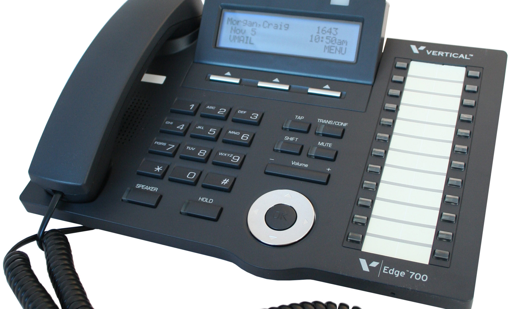
Do you have a legacy telephone system and are looking for a new vendor? We are ready to serve!!! Our seasoned Technicians work on Vertical, Comdial, Nortel, Vodavi, Toshiba, AT&T, Avaya, Lucent, Panasonic, NEC and many others.
800-821-2686
